RTR500BM for Windows
Introduction
RTR500BM for Windows is software that enables the user to perform the mobile communication settings, Remote Unit registration, warning settings, etc. in an RTR500BM via PC connected by USB.
- RTR500BM devices can be also be managed by using our dedicated smartphone app. For details about making settings with the smartphone app, see [T&D 500B Utility Mobile App] in this Help.
- Data can be viewed and warnings can be monitored using T&D's cloud service. For details see [T&D WebStorage Service] in this Help.
- Warning notifications can be sent via SMS or email. See [Current Readings / Warning Settings] - [Warning Transmission] for details. (The SMS function is supported by firmware version R.01.00.06 or later, software version 2.14 or later)
- This section explains how to use the RTR500BM for Windows. For details about the device itself such as explanations of the LED screen and power, see [RTR500BW/500BM/500BC] of this Help.
- RTR500BM for Windows may be referred to as "Windows software" in this Help.
| Compatible Products | |
|---|---|
| Base Units | RTR500BM Discontinued: RTR-500MBS-A* |
| Remote Units | RTR500B Series Data Loggers: RTR501B/502B/503B/505B/507B (including L types) RTR-500 Series Data Loggers*: RTR-574/576 (including S types), Discontinued: RTR-501/502/503/507S/505-Pt/505-TC/505-mA/505-V/505-P (including L types) |
| Repeaters | RTR500BC Discontinued: RTR-500* |
| * RTR-500 series models do not have Bluetooth capability. | |
Getting Ready
Installing the Software
Download the software from the T&D Website and install it to your PC.Opening RTR500BM for Windows will open the launcher window.
T&D Website > Software > RTR500BM for Windows
for EU Model
for US Model
Preparing a destination for data transfer:
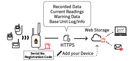
If you are using T&D WebStorage Service
Log in to T&D WebStorage Service, and add your device by serial number and registration code. If you do not already have an account, create one using "New User Registration".
(For details see: [T&D WebStorage Service])
If you are NOT using T&D WebStorage Service
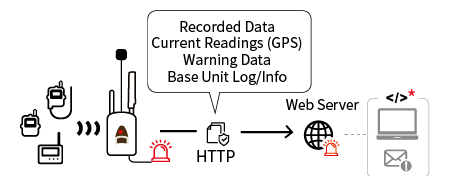
You can use your own Web or FTP server as the destination.
Necessary for Web Server:
- Web Server (HTTP/HTTPS)
- Web Application (to receive data from Base Unit)
- Root Certificate (for HTTPS)
Necessary for FTP Server:
- FTP Server
- FTP Account (User ID/Password)
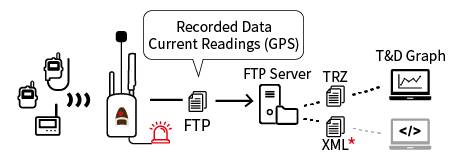
*Recorded data (TRZ format) can be analyzed using the T&D Graph software, but it is necessary for the customer to create a program to visualize the current readings data (XML format).
- It is not possible to send recorded data and current readings data to both a Web server and an FTP server.
- It is possible, however, to send recorded data to your FTP server and other data (current readings, warning data, and settings info) to T&D WebStorage Service. It makes it possible to monitor current readings and warnings on T&D WebStorage Service while storing recorded data locally.
- Communication via proxy is not supported.
- Communication specifications for the RTR500B Series, as well as, file formats for Current Readings Files and Recorded Data Files (XML) are available free of charge to our customers; please contact your local Distributor.
Things Necessary for Using a SIM Card
Prepare a SIM card that meets the requirements and insert it in the device.See [RTR500BW/RTR500BM/RTR500BC] - [SIM Card Preparation] for the requirements.
Getting Remote Units and Repeaters Ready
For details about using Remote Units see [ RTR501B/502B/503B/505B/507B] and/or [ RTR-574/576] in this Help.For details about using Repeaters see [ RTR500BW/500BM/RTR500BC] in this Help.
Base Unit Settings
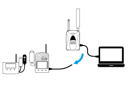
From the launcher window, open the RTR500BM Setting Utility and connect the RTR500BM to your computer via USB. The Base Unit Settings window will appear.- For a rough guide to necessary settings, open the [User's Manual] from the Launcher Window Menu.
- Use the supplied AC adaptor to supply power when making settings.
- In order to prevent unnecessary or unexpected data transmission, please leave the operation switch on the side of the RTR500BM to the STBY position until the units have all been set up and ready for communication. (See: [Device Installation])
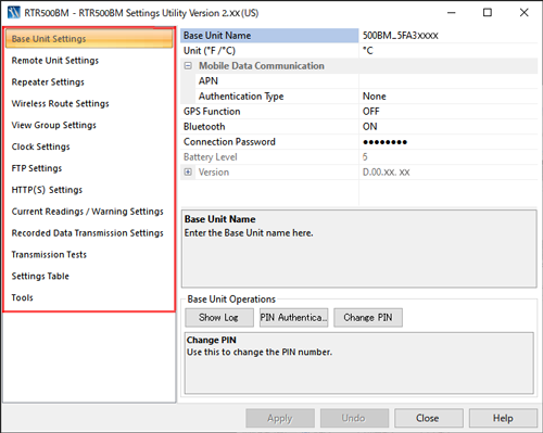
| Menu | Main Contents |
|---|---|
| Base Unit Settings | Base Unit Name, Temperature Unit, Mobile Data Communication (APN, Authentication Type, User Name, Password), GPS Function, Bluetooth, Battery Level, Version Info, Show Log, PIN Authentication, Change PIN |
| Remote Unit Settings | Registration to Base Unit and Deletion, Properties (settings changes), Recording Start, Download of Recorded Data |
| Repeater Settings | Registration to Base Unit and Deletion, Properties (settings changes) |
| Wireless Route Settings | Test Wireless Signal Strength, Wireless Route Settings (Auto/Manual) |
| View Group Settings | Add or Delete Displayed Groups, Change Names |
| Clock Settings | Base Unit Clock Settings (Current Time, Time Zone, Date/Time Format, Auto-Adjustment, SNTP Server Settings) |
| FTP Settings | FTP Server Settings (IP Address, ID, Password, Port Number, etc...) |
| HTTP(S) Settings | Specify and Make Settings for Data Transfer Destination (T&D WebStorage Service or your own web server) |
| Current Readings / Warning Settings | Auto Transmission of Current Readings (Interval and Method), Warning Monitoring Settings (Monitoring Interval, Contact Output Warning, Warning Transmission) |
| Recorded Data Transmission Settings | Auto Transmission of Recorded Data (Transmission Schedule, Interval, Method, File Name Settings, Data Range After Restart) |
| Transmission Tests | Current Readings Transmission, Warning Transmission, Recorded Data Transmission, GPS Operation, External Contact Output Test |
| Settings Table | Base Unit Info (Device Version, MAC Address, Registration Code, IMEI, etc...) |
| Tools | Acquisition of Device Info (Remote Unit / Repeater), Initialization of Device (Remote Unit / Repeater / Base Unit), Base Unit Settings History, Output Log and Settings |
| Base Unit Name | RTR500BM_Serial No. |
| Bluetooth | ON |
| Connection Password (for Bluetooth) | password |
| Auto Transmission of Current Readings | ON / Interval: 10 min. |
| Auto Transmission of Recorded Data | ON / Once daily (triggered by and depending on the time of first communication between the Base Unit and the mobile or Windows app) |
| Warning Monitoring | OFF |
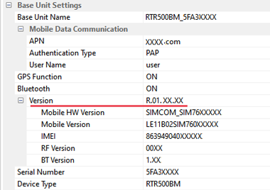
Base Unit Settings
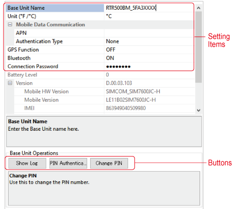
- Base Unit Name
-
Displayed as Model_Serial Number.
When using multiple Base Units the name can be edited for easier identification.
Base Unit Names will be applied as follows:- In warning emails
- In the T&D WebStorage Service Data View screen (in Current Readings file names and within the files themselves)
- In Recorded Data file names and within the files themselves
- Mobile Data Communication
-
Enter the SIM card information.
APN: Enter the Access Point Name (APN) for mobile data communication.
Authentication Type: Enter the authentication type for mobile data communication if any.- User Name / Password: Enter the user name and password for mobile data communication.
- If you have questions or trouble, please contact the issuing company or the place where you purchased the SIM card.
- GPS Function
-
By turning ON, GPS information will be added to the Current Readings file (xml).
- To use this function, also turn on the [Auto Transmission of Current Readings] in [Current Readings / Warning Settings], and specify the transmission method.
- Please purchase a GPS antenna separately.
- It is necessary for the customer to create a program to visualize the GPS data.
- It is possible to download GPS data in CSV/GPX formats from the [Devices] menu of T&D WebStorage Service.
- Bluetooth
-
Select ON to use Bluetooth communication.
- Connection Password
-
Enter a password here for connecting to a Base Unit via Bluetooth.
- Passwords must be alphabet or numerals from 6 to 64 characters.
- If you forget the password, reset it by connecting the Base Unit to a PC via USB and reset using this screen.
- [Show Log] Button
-
This opens the Base Unit Log window. Please refer to the log for investigation when an error occurs, etc. (See [Base Unit Logs])
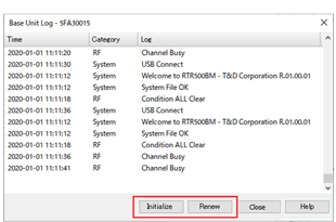
[Initialize] button: This initializes the log inside the Base Unit.
[Renew] button: This retrieves the most recent log from the Base Unit. - [PIN Authentication] button
-
To use the PIN authentication check ON and enter any number (4 digits).
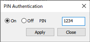
- This is a passcode to prevent theft or loss of the device or service, or unauthorized use by a third party.
- [Change PIN] button
-
This allows you to deactivate the currently set PIN number and set a new PIN number.
- If you enter the wrong PIN a certain number of times in a row, the SIM card will be locked and you will not be able to use the Base Unit. Enter your PUK (personal unblocking key) and a new PIN to unlock the card. The PUK code is an 8-digit number that can usually be found on the package of the SIM card.
- If you don't have the package or cannot find the PUK code, please contact your carrier for help.
- If the wrong PUK code is entered a certain number of times in a row, the SIM card will become permanently blocked and unrecoverable, requiring a new SIM card.
- Battery Level
-
When running on batteries, the battery level will be displayed in levels from 0 to 5.
3-5: OK
1-2: Change batteries (Communication errors may occur.)
0: No battery power (Communication will be interrupted which may cause loss of recorded data.) - Version
-
You can check the device version information and IMEI.
- When purchasing a SIM card, you may be asked for the IMEI number.
Remote Unit Settings
Up to 20 Remote Units can be registered to each Base Unit.
Upon registration or upon the start of a new recording session, all recorded data stored in the Remote Unit will be deleted. Make sure to download any recorded data you wish to save before making new recording settings. (For details see: Other Data Collection Methods).
Communication at Remote Unit Registration and Deletion
Settings Window
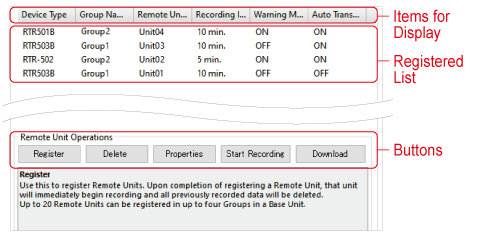
- Items for Display
-
Here you can change the items to be displayed and the order in which they are displayed.
- Right-click on the window and select [Display Item Settings] to make changes.
- Drag and drop the item left and right to change the order as desired.
- Registration List
-
This is a list of all Remote Units registered in the target Base Unit.
- [Register] Button
-
This opens the window that allows you to register data loggers to the target Base Unit as Remote Units.
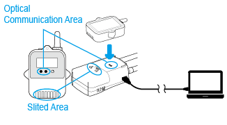
- If the data logger requires optical communication, connect the Base Unit with a USB cable to your PC and place the logger face down on the Base Unit.
- For RTR-574/576 loggers, connect directly to your PC with a USB cable.
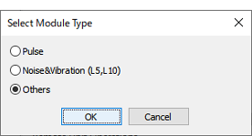
- If the logger is an RTR505B or RTR-505, a message box will appear for you to [Select the Measurement Item]. Click the suitable usage and click [OK] to open the settings screen. (This message will not appear if an Input Module is already connected.)
- [Delete] Button
-
Select the target Remote Unit from the registration list and click the button to open the "Delete Remote Unit" window.
When the Remote Unit is connected to a PC in the same way as during registration, the registration information in the Remote Unit will be deleted. When the process of deleting the registration information on the Base Unit is completed, the message "Success" is displayed and the targeted Remote Unit disappears from the list.- Recorded data will also be erased.
- If you are using the Shift/Ctrl key to select more than one Remote Unit, connect the next Remote Unit when [Initialized] is displayed for the currently connected device.
- If a Remote Unit cannot be connected to the PC because it is not at hand or is not working properly, select [Cancel] to delete the registration information in the Base Unit and finish the process. In this case, the registration information and recorded data will remain in the Remote Unit.
Unintended communication results may occur if a Remote Unit with registration information remaining in it is left within the radio communication area of a Base Unit for which communication is enabled. Make sure to initialize Remote Units from the [Tools] Menu. - [Properties] Button
-
Here Remote Unit settings changes can be carried out.
Select the target Remote Unit from the list and click the button.- To change a grayed out item, first delete the device from the registration list and register it again.
Setting Items for RTR505B, RTR-505
Setting Items for RTR-574/576 - [Start Recording] Button
-
Here you can select a Remote Unit, make settings for the recording interval and the recording start date and time and start recording.
- If the set date and time for starting recording is too close to the current date and time, an error will occur.
- The Remote Unit will go into waiting mode and [REC] will blink in the Remote Unit LCD until recording begins.
- [Download] Button
-
Here you can download and save recorded data from Remote Units to a PC via wireless communication.
In the Downloading Recorded Data window, select the Remote Unit(s), specify the storage location, file name, and downloading range, then click [Start] to start downloading.
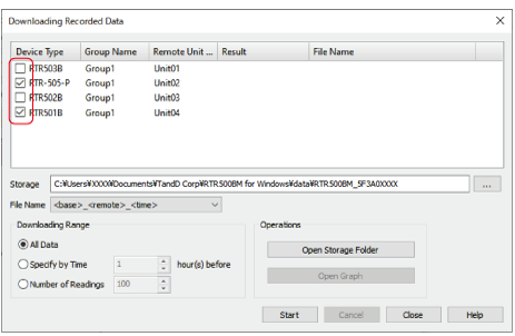
- If you do not specify the storage location, a folder with the Base Unit name will be automatically created. (Default Storage Location: MyDocuments\TandD Corp\RTR500BM for Windows\data )
- If you specify a file name that does not contain time, the file will be overwritten.
- Downloading Range:
All Data: This will download all recorded data in the Remote Unit. One logger at full data capacity will take about 2 minutes and 20 seconds to download to a PC. If there are any Repeaters the communication time will increase. Specify by Time: Download only data from the set number of hours before until the most recently recorded data. (In units of 1 hour)
Number of Readings: Download the specified number of readings back from the most recently recorded data.
Number of Readings: Download the specified number of readings back from the most recently recorded data. - After downloading is complete, you can select operations from the [Open destination folder] and [Open graph] buttons.
Setting Items
- Serial Number
-
This is the Remote Unit serial number.
- Wireless Group
-
Enter a Group Name for each frequency channel being used between sets of Base Units, (Repeaters) and Remote Units. If you wish to register a logger to an already registered Group, select the name of the target Group.
- Remote Unit Name
-
Displayed as Model_Serial Number.
When using multiple Remote Units the name can be edited for easier identification.
Remote Unit Names will be applied as follows:- In warning emails
- In the T&D WebStorage Service Data View screen (in Current Readings file names and within the files themselves)
- In Recorded Data file names and within the files themselves
- Remote Unit Number
-
The numbers are assigned automatically in order of registration.
- Communication Frequency Channel
-
Set a frequency channel for wireless communication to be used by Base Unit, (Repeaters), and Remote Units.
In each Wireless Group up to four frequency channels can be set for use with one Base Unit.- The frequency channels can be set from 0-21 for US Model and 0-11 for EU Model. (For details see: FAQs - [RTR500BM Settings] - [Q. When there are multiple Base Units being used in the same area, what is the best way to assign frequency channels?])
- When more than one Base Unit is registered, make sure to select channels that are far apart in order to prevent interference of wireless communication between Base Units.
- To make changes after having finished registration, it is necessary to delete all Remote Units and Repeaters with the same frequency channel setting from the Registration List and then register them again.
- Ch.1, Ch.2...
-
The measurement item for each channel is shown here.
- Recording Mode
-
Endless (Will overwrite the oldest data when capacity is full)
- Recording Interval
-
Select from the 15 possible choices. (1, 2, 5, 10, 15, 20, 30 sec / 1, 2, 5, 10, 15, 20, 30, 60 min)
If the interval is changed, all recorded data stored in the Remote Unit will be deleted.
Below are some examples of recording intervals and maximum recording times.RTR501B/502B/
505BRTR503B/507B,
RTR-574/576Recording Interval 1 sec 4 hr and 26 min 2 hr 13 min 30 sec 5 days 13 hr 2 days 18 hr 15 min. 166 days 16 hr 83 days 8 hr 60 min. About 1 year and 10 months About 11 months - Warning Monitoring
-
Switch to ON to monitor for warnings, and set the "Warning Judgment Time". When a warning condition is detected, a warning is issued only after the judgment counter expires.
By setting to OFF, that unit will be excluded from monitoring for warnings.- Settings can be made in each channel for "Upper and/or Lower Limits". When an out-of-limit measurement is detected and continues for the set Judgment Time, a warning will be issued. (The set limit values are not sent with the warning message.)
- Additional Monitoring Items for RTR505B
Event: A warning will be issued when the rising or falling pulse continues for the set Warning Judgment Time. (resolution:1 sec)
Pulse: Settings can be made for upper and lower limits for pulse measurements taken during the set recording interval.
- Auto Transmission of Recorded Data
-
Select whether to enable automatic downloading of recorded data to the Base Unit.
- Auto-download / sending of recorded data will not occur for those Remote Units that are set to OFF.
- Bluetooth
-
Switch OFF to disable the Bluetooth communication function.
- Bluetooth Passcode
-
Set a passcode (4-8 digit number) to be used for Bluetooth communication.
- Passcode can prevent unauthorized access and operation via Bluetooth from other mobile devices.
- The same passcode can be used for all devices.
- To check the current passcode, use the T&D 500B Utility mobile app and go to [Nearby Devices (Base Unit)] via Bluetooth - [Registered Devices (Remote Unit)] – [Bluetooth] setting – [Passcode] input field.
- If you cannot find the passcode, initialize the Remote Unit (or Repeater) from the [Tools] menu, and then re-register it.
Setting Items for RTR505B, RTR-505
- After making a setting, check the Remote Unit LCD to make sure everything is displayed correctly. (For details see: [RTR501B/502B/503B/505B/507B] - [RTR505B Display Examples by Input Module]).
- To replace an input module with another type, you must first delete the Remote Unit registration from the Base Unit, initialize the Remote Unit, and then register it with the new module.
- Sensor Type (TCM-3010, PTM-3010)
-
Select the type of sensor connected to the input module.
For TCM-3010: K, J, T, or S
For PTM-3010: Pt100 or Pt1000- When replacing a sensor with a different type, make sure to change this setting to reflect the type which is connected.
- Recording Method (VIM-3010, AIM-3010)
-
Make settings for the recording method for measurements.
Instantaneous Value: Records the instantaneous value measured at each recording interval.
Average Value: Records the average value of the measurements taken every second within the recording interval. - Scale Conversion Equation (VIM-3010, AIM-3010, PIC-3150)
-
Make settings for when using scale conversion. This has no reflection on what is displayed on the LCD display of the Remote Unit.
Use y=ax+b: Select this when the values for both the slope (a) and intercept (b) are already known.
Specify 2 points: Select this when both the input values from the sensor and the post-conversion values are known at two points. (See the sensor user's manual for details)- If desired, a string of characters can be input directly to show the "Unit of Measurement" for the value after scale conversion.
- When viewing the recorded data, if it includes both pre- and post-conversion data, the pre-conversion data will also be displayed using the same conversion rules as for the post-conversion data.
- If the graph and units are not displayed correctly in the browser after changing the scale conversion equation, please try the following operations.
- Refresh the web browser.
- Reset the graph data when using the T&D WebStorage Service (For how to reset data, see: [T&D WebStorage Service] - [
 Devices] - [Settings] Button (Remote Unit) - [Reset Data] button).
- Preheat / Preheat Time (VIM-3010)
-
Select ON if you wish to control the sensor power supply. It transmits a preheat signal that is synchronized with the recording interval to turn sensors ON before and OFF after measuring and recording.
- Because the sensor does not measure except during a recording session, the Remote Unit LCD will refresh at each recording interval.
- The length of preheat time will differ upon your sensor. Please check the specifications for the sensor being used.
- If the set preheat time is equivalent to or longer than the recording interval, current will be continually supplied to the sensor.
- Measurement Range (VIM-3010)
-
Make settings here for the range of measurement. The Remote Unit LCD will change to reflect the set measurement range.
V Range:
Measurement Range: 0 to 22V
Resolution: Automatically changes from 0.1mV to 10mV according to the input signal.
Display Unit: V (fixed)
mV Range:
Measurement Range: 0 to 999.9mV
Resolution: Automatically changes from 0.1mV to 0.4mV according to the input signal.
Display Unit: mV (fixed)- If this setting is changed, all recorded data stored in the Remote Unit will be deleted.
- LCD Display (PIC-3150)
-
Specify the value for display in the Remote Unit LCD.
Pulse Rate: The pulse count for recording interval period will be displayed. The display will be refreshed every one-sixtieth of the recording interval (at minimum of every one second).
Total Pulse Count: The pulse count (0 to 9999) since recording start will be displayed. The refresh interval is 1 second. - Pulse Signal Type (PIC-3150)
-
Make settings here for the pulse signal type to be recorded.
Rising: Records the number of rising pulses during the set recording interval.
Falling: Records falling pulses during the set recording interval.- If this setting is changed, all recorded data stored in the Remote Unit will be deleted.
- Chattering Filter (PIC-3150)
-
If you wish to use the filter for eliminating chattering which occurs due to changes in polarity, this should be switched to ON.
ON: 15Hz or less
OFF: 3.5kHz or less
(when using square wave signals of 0-3V or higher)- If this setting is changed, all recorded data stored in the Remote Unit will be deleted.
- Target Item for Warning Monitoring (PIC-3150)
-
Select the target item from Pulse or Event (rising or falling) and judgment time for warning monitoring.
Display resolutions for monitoring each target item are follows:
Pulse: one-sixtieth of recording interval (minimum of one second)
Event: 1 sec
- Noise and Vibration
- Make settings for the sampling interval, calculation percentage and calculation time period.
Setting Items for RTR574/576
- Channels for Alternating Display (RTR-574)
- Select the items to be displayed in the Remote Unit LCD.
- LCD Display Items (RTR-576)
-
Select the items to be displayed in the Remote Unit LCD.
- Button Lock
-
Use to lock the Remote Unit operation buttons. If set to ON, only the DISPLAY button will be functional.
- Note: When "Button Lock" is OFF and you change the recording interval using the INTERVAL button on the unit, that change will not be reflected to the Remote Unit information stored in the Base Unit. The change will be applied to the recorded data set.
- Atmospheric Pressure Correction (RTR-576)
-
Measurement results of CO2 concentration are affected by atmospheric pressure. This function corrects for atmospheric pressure to achieve a more reliable CO2 concentration measurement.
This setting can be made by directly entering the pressure (hPa) at the measurement location, or by having the software calculate the estimated pressure at the altitude (meters) entered by the user. - Auto Calibration (RTR-576)
-
It is possible to calibrate the CO2 sensor either automatically or manually.
Refer to Calibration / Adjustment Function for the operation procedures and precautions.
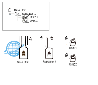
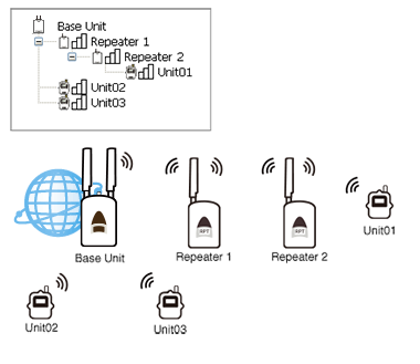
Repeater Settings
The wireless communication range can be extended by placing a Repeater in between a Base Unit and a Remote Unit.- Up to 5 Repeaters can be registered to each Group, and up to 4 Groups can be created.
- The wireless communication range, if unobstructed and direct, is about 150 meters (500ft).
- After adding or deleting a Repeater, go to Wireless Route Settings and carry out a radio signal strength test.
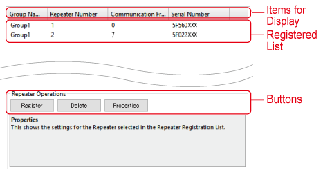
- Items for Display
-
Here you can change the items to be displayed and the order in which they are displayed.
- Right-click on the window and select [Display Item Settings] to make changes.
- Drag and drop the item left and right to change the order as desired.
- Registration List
-
This is a list of all Repeaters registered in the target Base Unit.
- [Register] Button
-
This opens the window that allows you to register Repeaters to the target Base Unit.
- [Delete] Button
-
Select the target Repeater from the registration list and click the button to open the "Delete Repeater" window.
When the Repeater is connected to a PC in the same way as during registration, the registration information in the Repeater will be deleted. When the process of deleting the registration information on the Base Unit is completed, the message "Success" is displayed and the targeted Unit disappears from the list.- If you are using the Shift/Ctrl key to select more than one Repeater, connect the next Repeater when [Initialized] is displayed for the currently connected device.
- If a Repeater cannot be connected to the PC because it is not at hand or is not working properly, select [Cancel] to delete the registration information in the Base Unit and finish the process. In this case, the registration information and recorded data will remain in the Repeater.
IMPORTANT
Unintended communication results may occur if a Repeater with registration information remaining in it is left within the radio communication area of a Base Unit for which communication is enabled. Make sure to initialize Repeaters from the [Tools] Menu. - [Properties] Button
-
Here Repeater settings changes can be carried out.
Select the target Repeater from the list and click the button.- To change a grayed out item, first delete the Repeater from the registration list and register it again.
Setting Items
- Serial Number
-
This shows the Repeater serial number.
- Wireless Group
-
Specify the Group to which the Remote Units are registered that you wish to add a Repeater.
- Repeater Name
-
Displayed as Model_Serial Number.
When using multiple Repeaters the name can be edited for easier identification. - Repeater Number
-
The numbers are assigned automatically in order of registration.
It will appear in the screen of the Repeater. - Communication Frequency Channel
-
Set the frequency channel for Repeater to the same one as the Remote Unit to which you wish to communicate.
In each Wireless Group up to four frequency channels can be set for use with one Base Unit. Up to 10 Repeaters can be registered to each Wireless Group.- The frequency channels can be set from 0-21 for US Model and 0-11 for EU Model. (For details see: FAQs - [RTR500BM Settings] - [Q. When there are multiple Base Units being used in the same area, what is the best way to assign frequency channels?])
- When more than one Base Unit is registered, make sure to select channels that are far apart in order to prevent interference of wireless communication between Base Units.
- To make changes after having finished registering, it is necessary to delete all Remote Units and Repeaters with the same frequency channel setting from the Remote Unit Registration List and then register them again.
- LCD Display
-
Up to 3 alpha-numeric characters can be set to help identify the group. (optional)
- This will appear in the screen of the Repeater.
- Bluetooth
-
Switch OFF to disable the Bluetooth communication function.
- Bluetooth Passcode
-
Set a passcode (4-8 digit number) to be used for Bluetooth communication.
- Passcode can prevent unauthorized access and operation via Bluetooth from other mobile devices.
- The same passcode can be used for all devices.
- To check the current passcode, use the T&D 500B Utility mobile app and go to [Nearby Devices (Base Unit)] via Bluetooth - [Registered Devices (Repeater)] – [Bluetooth] setting – [Passcode] input field.
- If you cannot find the passcode, initialize the Remote Unit (or Repeater) from the [Tools] menu, and then re-register it.
Wireless Route Settings
Make wireless route settings here for communication between Base Units, Repeaters and Remote Units and carry out tests of signal strength between the various devices.- The wireless communication range, if unobstructed and direct, is about 150 meters (500ft).
- For more info about installation see: [Please Read First] - [About Installing Wireless Communication Devices] in this Help.
- Anytime you decide the installation points, add or delete devices, or communication errors continually occur, it is a good idea to make sure communication is stable and reliable by testing the signal strength of wireless communication between the Base Units, Repeaters and Remote Units.
The automatic route setting function cannot be used for wireless groups that include the RTR-500 Repeater.
- Wireless Routes
-
Select the way you wish to create wireless routes.
Auto: Communication is carried out using the best route from the previous communication result.
Manual: Communication will be carried out using the manually set route. To create or change a route, drag and drop Remote Unit and Repeater icons to the desired position within the wireless route where you would like them to be and click the [Apply] button.
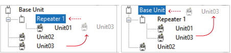
Left Figure: If you wish to move [Unit03] under the [Repeater 1] tree, drag the icon up into the Repeater 1 icon.
Right Figure: If you wish to move [Unit03] to directly connect with the Base Unit, drag the icon from the Repeater tree up into the Base Unit icon. - Wireless Group
-
Select the wireless route or wireless group of which you wish to test signal strength.
- Latest
-
When creating the wireless route automatically, the date and time of the last wireless communication is displayed.
- [Test Signal...] button
-
Clicking this will open the [Check Signal Strength] window.
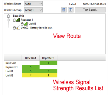
Specify the device to start, and close the screen when communication is completed. - View Route
-
The wireless route for the group selected from the Wireless Group list will appear here.
- The signal strength is shown in colored bars. Two or more green bars is ideal.
- A message will be displayed for devices with low battery power.
- Wireless Signal Strength Results List
-
The results for the wireless route and signal strength of the selected Wireless Group will be displayed here.
Green (3-5): Good
Yellow (1-2): Unstable
White (0): Error
View Group Settings
When using a cloud service or sending warning mails, etc., you can create "View Group" and add Remote Units to the Groups as desired.- Add or Delete View Groups, Change Names
- Settings can be made from the button at the top of the screen.
- Moving Remote Units between Groups
- You can move Remote Units by dragging and dropping their icons to a different Group.
Clock Settings
- Current Time
-
Set the time of the Base Unit either using the PC clock or by directly entering the date and time.
- Time Zone
-
Select the time zone where the device is being used.
- Daylignt Savins Time
-
Select this to automatically make adjustments for daylight savings time.
- Date / Time Format
-
Select from one of the six available patterns.
This will be used everywhere except in data file names. - Auto-Adjustment
-
Make sure this is set to ON.
Auto-Adjustment is a function to automatically adjust the date and time of the Base Unit using the SNTP server.- Clock adjustment is made when the Operation Switch is turned to the
position, as well as once a day while in the Run position.
- Clock adjustment is made when the Operation Switch is turned to the
- SNTP Server
-
Enter the address of the SNTP Server to be used for the Auto-adjustment of date and time; this will help to auto-adjust after a power failure.
EX: time-xx.nist.gov 111.111.111.111
FTP Settings
Make settings here when sending the current readings and recorded data to your FTP server.- FTP Server
-
Enter the "IP Address" or "Host Name" for your FTP Server.
EX: 10.0.1.55, ftp.example.tandd.com - FTP User ID
-
Enter your FTP User ID.
- FTP Password
-
Enter your FTP port number.
- FTP Port Number
-
Enter your FTP port number.
- Passive Mode
-
Select ON to use PASV mode.
- Character Encoding
-
Specify the character encoding for file names you wish to send to the FTP server.
- The character encoding used within Current Readings and Recorded Data Files cannot be changed.
HTTP(S) Settings
Make settings here when sending the current readings, recorded data, and warning data to T&D's cloud server or to your own web server.- Connection Destination
-
T&D WebStorage Service: Cloud Service with English display
Ondotori Web Storage: Cloud Service with Japanese display
Custom: Use your own web server- If you select Custom, make sure to enter the destination address, port number and destination path.
- When using an HTTPS server, import the root certificate (DER format) required for connection to the Base Unit.
- Communication Interval
-
The Base Unit periodically communicates with the server to check for pending settings. You can select the interval time from the 11 choices (OFF, 5, 10, 20, 30 min, 1, 2, 4, 6, 12, 24 hours).
- Default Settings: 10 min.
- When changing the Base Unit Settings from the mobile app T&D 500B Utility via T&D WebStorage Service, the settings will be applied at a short interval if you set a short interval here.
- If you select [OFF], pending settings will be applied to the Base Unit at the timing of sending current readings or recorded data to the server.
Current Readings / Warning Settings
Make settings here for auto transmission of current readings and for warning monitoring.If SMS does not appear in the [Warning Transmission] field:
- Update your Windows software to the latest version.
- Update the RTR500BM firmware to the latest version. (See: Checking and Updating the Firmware Version)
- Auto Transmission of Current Readings
-
Set to ON to have current readings sent automatically.
- Transmission Interval
-
Select from the 11 choices (2, 5, 10, 20, 30min, 1, 2, 4, 6, 12, 24 hours) for transmission interval of current readings.
- Transmission Method
-
Select the transmission method for sending current readings.
- If you wish to send data to T&D WebStorage Service or your own web server, select HTTP(S). T&D WebStorage Service allow you to monitor the transmitted current readings via a web browser.
- When sending by FTP, enter the file name and destination folder.
- Warning Monitoring
-
Switch to ON to monitor for warnings.
- Warning Monitoring will not be carried for those Remote Units which have Warning Monitoring set to OFF.
- T&D WebStorage Service display alerts or warning notifications in the web browser.
- Warning Monitoring Interval
- Select the interval (2 or 5 minutes) for monitoring for warnings.
- Condition for Warning Output (Contact Output)
-
Here you can check the warning conditions of the contact output.
- Attach an alarm device such as a siren, buzzer, or magnetic contactor to the external contact output terminal.
- When [Battery Warning] is checked, in addition to low battery of the Remote Unit and Base Unit, power failure/insufficient power supply voltage of the external power supply connected to the Base Unit will also be monitored.
For details see: [Details of Operations] - [About Warning Monitoring] - [Warning Contact Output Operations]
- Warning Transmission
-
If you wish to receive notifications when a warning occurs or recovers, select the transmission method (HTTP(S) only, SMS only, or both HTTP(S) and SMS).
HTTP(S): Warning data will be sent to the specified HTTP(S) server, such as T&D WebStorage Service. T&D WebStorage Service will display an alert in the Alert View window and send a warning email to the specified address(es). (See: [T&D WebStorage Service] - [Alert View])- Warning mail settings can be made for up to 4 addresses from the T&D WebStorage Service > Account Management.
- Warning transmission via FTP is not supported.
SMS: SMS messages will be sent directly to the specified phone number(s).
- When selecting SMS, you can set up to 4 recipients and warning conditions for each recipient. In the recipient field, enter the phone number starting with the country code (without hyphen and space).
EX:
For US (country code +1), area code "518" and phone number "xxx-xxxx", enter "+1518xxxxxxx".
For Germany (country code +49), area code "030" and phone number "xxxx-xxxx", enter "+4930xxxxxxxx". - SMS notification cannot be configured in the mobile app T&D 500B Utility. Also, when SMS notification is enabled, it is not possible to change warning settings from the mobile app.
Recorded Data Transmission Settings
Use this to automatically download recorded data from target Remote Units at a set date/time or interval and have that data sent to the server.
- Auto Transmission of Recorded Data
-
To carry out auto-downloading/sending of Recorded Data, select ON.
- Auto-downloading will not be carried for those Remote Units which have Auto-Downloading of Recorded Data set to OFF.
- Transmission Scheduling Method
-
Transmit by day and time: Up to eight patterns can be set.
If you select more than one date and time, make sure that they are one or more hour apart.
Transmit by Interval: Select from the 5 choices (30min, 1, 2, 3, 4 hours) for Sending Interval of recorded data.
If you select more than 1 hour, you can also specify in 10-minute increments.
Recorded data will be sent at the specified interval(s) starting from 0:00.
Note
The default setting is "Transmit by day and time" and Schedule 1 "Every Day (on the hour)", which will be the next full hour after the first communication between the device and the app (mobile or Windows) + 30 minutes.
Examples:
If the first communication occurred at 13:00, the next full hour after 30 minutes will be 14:00. (Default Transmission Schedule: Every Day 14:00)
If the first communication occurred at 13:31, the next full hour after 30 minutes will be 15:00. (Default Transmission Schedule: Every Day 15:00) - Transmission Method
-
Select the transmission method for sending the automatically downloaded recorded data.
If you are using the T&D WebStorage Service or your own web server, select HTTP(S).
When sending by FTP, specify the destination folder as necessary. - File Name
-
Select from the 9 choices for File Name settings.
EX: If you select <base>_<remote>_<time>, the file name will be [Base Unit Name_Remote Unit Name_Date/Time].- If you specify the file name that does not contain time, the file will be overwritten.
- The Base Unit Name which was set in the [Base Unit Settings] menu will appear in the file name.
- Data Range After Restart
-
Data after Restart Only: This will send only the data recorded after moving the Operation Switch to
RUN and operation started.
All Data: This will send all recorded data.
While the Operation Switch is in the STBY position, recorded data can not be downloaded or sent.
Transmission Tests
After registering and changing settings, execute the necessary tests, if a test fails, see the explanation and error codes and make settings changes as necessary.
(For details see: Error Code List)
Test the device in the same condition as when it was set up (connected to the PC via USB, with the Operation Switch in the STBY position).
- If you are using T&D WebStorage Service, make sure to first register your Base Unit to T&D WebStorage Service before carrying out any tests.
- In the transmission test window, any improperly made settings or unmade settings will appear in red.
- The test data will not be displayed in T&D WebStorage Service.
Transmission Test of Current Readings/Warning Reports/Recorded Data
If the data destination is T&D WebStorage Service, you will see "Success" when the data is sent successfully.
When specifying a destination other than T&D WebStorage Service, see if the specified server has received the test data.
GPS Operation Test
Location information will be displayed in DMM format.
Latitude (North or South): ddmm.mmmm
degree: dd, minute: mm, 1/10000 minute: mmmm
Longitude (East or West): dddmm.mmmm
degree: ddd, minute: mm, 1/10000 minute: mmmm
External Contact Output Test
Confirm that the warning device connected to the external contact output operates properly.
Settings Table
Here you can see Base Unit Settings (including Mobile Version, IMEI, Registration Code, etc...) and view settings contents in table form.
Tools
This menu allows you to obtain device information and initialize the device.
- Get Remote Unit Info
-
This retrieves and shows device information for the connected Remote Unit.
- Initialize a Remote Unit
-
This returns the Remote Unit to its original factory default settings.
(See: [Notes on Initializing Remote Unit/Repeater]) - Get Repeater Info
-
This retrieves and shows device information for the Repeater which is connected via USB to the PC.
If the device is running on batteries, the battery level will be displayed in levels from 0 to 5.
3-5: OK
1-2: Change batteries (Communication errors may occur.)
0: No battery power (Communication will be interrupted which may cause loss of recorded data.) - Initialize a Repeater
-
This returns the Repeater which is connected by USB cable to the PC to its factory default settings.
(See: [Notes on Initializing Remote Unit/Repeater]) - Initialize a Base Unit
-
This returns the Base Unit connected by USB cable to the PC to its factory default settings.
- Mobile data communication settings (such as APN and PIN authentication code) will remain unchanged.
- Settings History
-
This shows the setting info for Base Units according to their serial number and last update date.
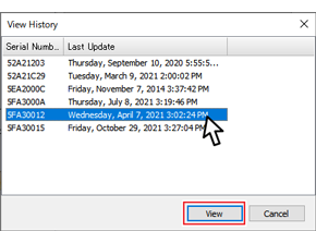
- Select and click the [View] button to open the [Settings Table] window where you can check the Base Unit information.
- Output Log and Settings
-
The operation log and device settings can be output as text (.txt) for the Base Unit connected via USB.
Select the target unit from the list of connected Base Units and click the button.
Notes on Initializing Remote Unit/Repeater
- After initializing a Remote Unit or Repeater, make sure to delete it from the registration list in Remote Unit Settings or Repeater Settings. Failure to do so may cause a communication error or operation error.
- Once initialized, the setting information and recorded data in the device will be deleted and cannot be restored.
- When initializing the Remote Unit that uses a High Precision Temp-Humidity Sensor SHA-3151, SHB-3101, Thermocouple Module TCM-3010, Pt Module PTM-3010, 4-20mA Module AIM-3010, or Voltage Module VIM-3010, if you were making adjustments to the measurements (via Adjustment Tools), the setting has been saved in the sensor/module and will remain even if the Remote Unit is initialized. To reset the adjustment setting, use the Adjustment Tools software and perform the initialization.
Device Installation
After each communication test is successfully completed, place the Base Unit, Remote Units and, if necessary, Repeaters in their actual positions.
-
Disconnect the Base Unit from the computer and connect it to the power supply at the installation site.
External power can be used such as the supplied AC adaptor. or car battery using an optional battery connection adaptor. (See: [RTR500BW/500BM/500BC] - [Power] in this help) -
Turn the Operation Switch on the side of the RTR500BM to the Run position.
The start-up process will take up to 2 minutes (depending on the number of registered Remote Units and Repeaters).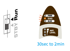
DIAG blinking (starting up) -
When the start-up process is completed, functions will start.
After 1 to 5 minutes, the recorded data set in the Data Range After Restart will be downloaded from the Remote Unit and automatically sent to the specified destination.
Normal LED Display -
Access the destination server (T&D WebStorage Service or other web or FTP server), and check if the recorded data has been received successfully.
If the DIAG is ON or blinking after the startup time has elapsed, please review the settings. (See: [RTR500BW/500BM/500BC] - [RTR500BM] - [LED Display and Operation Switch] in this help.)
Other Data Collection Methods
By using T&D Tools you can download and save data directly to a PC via Bluetooth or optical communication.
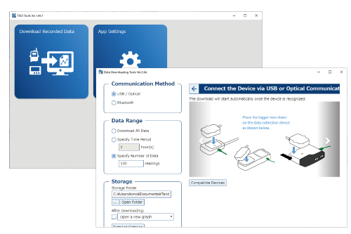
Open T&D Tools - Data Downloading Tools. Select the method (USB, Optical, Bluetooth) to communicate with Remote Units, select the download range and make settings for the storage location, etc... and start downloading.
T&D Website > Software > T&D Tools
Checking and Updating the Firmware Version
Bluetooth communication will be between the Remote Unit and the PC. A search for Remote Units nearby the PC will occur and that are found will appear in a list.
- The firmware update requires a USB connection between the RTR500BM and a PC.
- During a firmware update, monitoring for current readings and warnings as well as data collection cannot be executed.
By opening the [Settings Table] in the Settings Utility you can check the firmware version of the Base Unit connected to the PC via USB.
In the launcher window click [Update Information] to open the T&D "Check for Updates" Tool*.
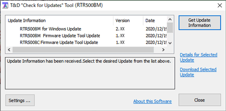
- Update Information
- This shows program versions and date of update.
- [Settings] Button
-
Here you can select whether or not to automatically check for the latest software version information on the Internet when the Setting Utility is started.
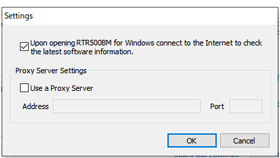
- If you wish to use a proxy server to check and update the firmware, check [Use a Proxy Server] and enter the IP address and port number.
- [Get Update Information] Button
-
Use this to get the settings info for the Last Page.
- [Details for Selected Update]
-
Clicking here will take you to T&D Website > News > Update Info where you can view details for the program that you selected.
- [Download Selected Update]
-
Clicking here will take you to T&D Website > Software Download where you can download the update for the program that you selected. Precautions and update procedure info is also available here.
Details of Operations
About Sending Current Readings
Basic Process
Current Readings will be sent at the interval set via the smartphone app or the Windows software.- The RTR500BM communicates via wireless communication with all registered Remote Units and gathers their current readings.
-
The readings are then sent by the set transmission method at the set interval.
When another process occurs simultaneously the following operations take place.
- If the sending of current readings coincides with a scheduled auto-downloading of recorded data, the auto-downloading process will take precedence and the current readings will be sent after downloading has been completed.
- If the sending of current readings coincides with the transmission of a warning notification, the warning notification will be completed first and then the sending of current readings.
Conditions for Transmission
The RTR500BM can only send the current readings if all of the following conditions are met.
- All settings for the Auto Transmission of Current Readings in the RTR500BM have been completed.
- The device is working on batteries or external power supply.
- The Operation Switch is in the Run position.
Contents of Transmission
The current readings data transmitted includes up to 10 recorded values for each Remote Unit.
The number of readings that can be reflected in a current readings graph display differs depending on the model and is as follows:
| Model | Number of Readings |
|---|---|
| RTR501B, RTR-501. RTR502B, RTR-502, RTR505B (other than pulse measurement), RTR-505 (other than pulse measurement) |
10 readings |
| RTR503B, RTR-503. RTR507B, RTR-507S, RTR-576 | 5 readings |
| RTR505B (for pulse measurement), RTR-505-P (for pulse measurement), RTR-574 | 4 readings |
| ∗ The shortest interval at which RTR500BM can create data files of Current Readings to transfer to the server is 30 seconds. Therefore, even if the recording interval for a Remote Unit is less than 30 seconds, the interval of Current Readings Data which can be displayed is 30 seconds. ∗ For RTR-574/576 (including S type), the recorded data records average values and the current readings data records instantaneous values according to the set recording interval and transmits them as current readings data. Therefore when comparing Current Readings Data and Recorded Data (trz format), the times of measurements may differ and hence measurement readings may slightly vary. ∗ The above shows the maximum number of readings. Depending on the Remote Unit recording interval and the amount of time from the beginning of recording, the actual number of readings transferred may be less than maximum. |
|
If you need detailed information about the data format of current readings, please contact your local Distributor.
Operation Upon Current Readings Transmission Error
If an error occurs during the transmission of current readings, the RTR500BM will carry out the following:- After a 10 minute wait the process will begin again from the start (up to 2 times). Note however that if the sending interval is set to 10 minutes or less, resending cannot be performed.
- If during that 10 minute wait, the Base Unit is scheduled to send Current Readings, the resending process of the prior set of data will be canceled and the Current Readings will be sent at the scheduled time.
About Warning Monitoring
Basic Process
Monitoring for warnings will occur at the interval set via the smartphone app or the Windows software.
-
The RTR500BM communicates via wireless communication with all Remote Units which have been set for the monitoring of warnings and gathers all data necessary for sending a warning.
-
It will confirm if conditions have been met for the sending of a warning notification or that such conditions have been recovered from and if warranted will send the warning data to the server.
When another process occurs simultaneously the following operations take place.
- If the sending of a warning report coincides with a scheduled auto-downloading of recorded data, the auto-downloading process will take precedence and the warning report will be sent after downloading has been completed.
- If the sending of current readings coincides with the transmission of a warning notification, the warning notification will be completed first and then the sending of current readings.
Conditions for Transmission
Warning Notification can only be sent if all of the following conditions are met:
- All device settings (Base Unit and Remote Unit) for Warning Monitoring have been completed.
- The device is working on batteries or external power supply.
- The Operation Switch is in the Run position.
- Conditions for at least one of the [Types of Warning Reports] has been met or the conditions have changed to warrant a recovery message.
Types of Warning Monitoring
- Remote Unit Upper Limit / Lower Limit Exceeded
-
A measurement reading has been deemed to have exceeded the set Upper or Lower Limit for the set amount of time.
(Measurements that exceed the set Upper/Lower Limit but do not last for the set amount of time will not be judged as warning) - Remote Unit Sensor Error
-
Sensor Abnormality (no sensor connected, broken connection, etc...)
- Remote Unit Battery Level
-
Remote Unit battery level has reached low.
(One hour has passed since the battery warning mark on the LCD came on). - Base Unit Battery Level / External Power Warning
-
Base Unit battery level has reached low when it is operated on battery power alone.
Power failure of external power supply, insufficient supply voltage, etc.
Note: [Battery Warning] needs to be enabled in [Current Readings / Warning Settings] - [Warning Monitoring] - [Condition for Warning Output]. - Wireless Communication Error
-
Wireless communication with a Remote Unit has failed three consecutive times.
- Contact Input (Base Unit)
-
The external contact input has switched to ON.
(Judgment of ON (closed) or OFF (open) of the contact is decided when the state continues for 1 second or longer.)
Warning Contact Output Operations
During warning monitoring, if a warning is detected the contact output turns ON (circuit closed). During warning monitoring, when a recovery is detected, the contact output is turned OFF (circuit is open).
If both a warning and a recovery occur within the same warning monitoring interval, the contact output is turned ON (circuit closed) for 10 seconds at the timing of warning monitoring.
Operation Upon Warning Transmission Error
If an error occurs during the transmission of warning data, the RTR500BM will carry out the following:
- A retry will occur at the set warning monitoring interval after the failure of sending a warning report and this will continue until successful.
- Any warning(s) that occur during the resending of a failed transmission will also be included and sent.
In the [Monitoring / Warning Settings], when multiple SMS destinations are set for either [SMS only] or [both HTTP(S) and SMS] for [Warning Transmission] the device will consider the sending of the warning as a success even if it has only been successfully sent to one of the addresses.
About Auto-Sending of Recorded Data
Basic Process
Recorded Data will be automatically downloaded and sent at the interval set via the smartphone app or the Windows software.
-
The RTR500BM communicates via wireless communication with the target Remote Units and downloads their recorded data.
-
The recorded data is then automatically transferred.
All data for the first time or all data after a recording start is transmitted (depending on the initial data transmission range setting)
From the second time only the remaining new data not sent before will be sent.
Conditions for Transmission
The RTR500BM can only auto-send the recorded data if all of the following conditions are met.
- All necessary settings for Auto Transmission of Recorded Data have been completed in the RTR500BM.
- The device is working on batteries or external power supply.
- The Operation Switch is in the Run position.
- When communication occurs with Remote Units which have [Auto Transmission of Recorded Data] set to ON in Remote Unit Settings.
Operation Upon Recorded Data Transmission Error
If an error occurs during the transmission of recorded data, the RTR500BM will carry out the following:
- After 30 minutes have passed communication will be retried with only those units for which communication failed.
- The recorded data, including the range of the previous transmission error, is downloaded from the Remote Unit(s) when retransmitting.
Contents of Transmission
Sends the remaining data that was not sent the previous time.
Error Code List
General System| Error Code | Problem | Probable Cause and Solution |
|---|---|---|
| 10001 | SRAM Reading Writing Error | Try power cycling the device by removing the AC adaptor and batteries. If the error continues, the device may be damaged. |
| 10002 | EEPROM Reading Writing Error | |
| 10003 | Low Battery Power | Change batteries or use an external power source. |
| Error Code | Problem | Probable Cause and Solution |
|---|---|---|
| 20001 | Command Format Error | Your software and/or firmware version may not be supported. Please update them to the latest version. |
| 20003 | Unstable Operation | Try power cycling the device by removing the AC adaptor and batteries. If the error continues, the device may be damaged. |
| 20004 | Command in Progress | Please wait and try again. |
| Error Code | Problem | Probable Cause and Solution |
|---|---|---|
| 30001 | Failure to Initialize Mobile Communication Module | If the problem occurs repeatedly, it is either a power supply (and/or battery) problem, or a malfunction of the device. |
| 30002 | Mobile Communication Module Frozen | |
| 30003 | Communication Error with Mobile Communication Module | |
| 30004 | SIM Lock Error | |
| 30005 | SIM Unlock Error | |
| 30006 | SIM Card Locked | SIM card has been locked due to incorrect PIN. Enter PUK code. |
| 30007 | SIM Card Not Detected | |
| 30008 | SIM is Locked | |
| 30010 | PIN Not Match | |
| 30011 | Cannot Change PIN | Make sure the PUK code is entered correctly. |
| 30012 | Mobile Communication Network Error | Make sure there are no problems with APN settings, SIM Card Plan, cellular antenna connection. |
| 30013 | Mobile Communication Failure | |
| 30014 | Mobile Communication Failure | |
| 30151 | SIM PIN Locked | |
| 30152 | SIM PIN Unlocked | |
| 30500 | Unexpected Errors | Please contact your distributor if the error continues. |
| Error Code | Problem | Probable Cause and Solution |
|---|---|---|
| 40001 | Wireless Communication Busy | Another wireless communication is in progress. Please wait and try again. |
| 40002 | Wireless Communication Failure (Remote Unit) | Please try initializing and re-registering the Remote Unit. |
| 40004 | Wireless Communication Failure (Repeater) | Check conditions (such as the signal strength and battery status) of the Repeater to make sure wireless communication can be carried out. |
| 40005 | Wireless Communication Failure (Remote Unit) | Check conditions (such as the signal strength and battery status) of the Remote Unit to make sure wireless communication can be carried out. |
| 40006 | Wireless Communication Failure | Check conditions (such as the signal strength and battery status) of the Repeater to make sure wireless communication can be carried out. |
| 40007 | Recording can not begin because there are not enough seconds remaining before the scheduled recording start. | The amount of time before the set recording start date and time is too short. Please change the date and time for the recording start and try again. |
| 40009 | No data to download | |
| 40021 | Wireless communication channel is unavailable (channel busy). | Channel is busy. Move the device as far away as possible from noise emitting devices such as PCs. |
| 40099 | Unexpected Errors | Please contact your distributor if the error continues. |
| Error Code | Problem | Probable Cause and Solution |
|---|---|---|
| 50001 | Communication Error | Optical communication failed. Make sure the Remote Unit is placed on the Base Unit correctly. |
| 50002 | Command Parameter Error | If the problem occurs repeatedly, it is a malfunction of the device. |
| 50003 | Response Error | Optical communication failed. Make sure the Remote Unit is placed on the Base Unit correctly. If the error persists, unplug the USB cable and reboot the software and try again. |
| 50090 | No data to download. |
| Error Code | Problem | Probable Cause and Solution |
|---|---|---|
| 60001 | GPS Function is turned OFF | GPS setting is OFF so you cannot obtain GPS data. |
| 60002 | GPS Data Not Received | Install the antenna in an open area where the GPS signals are not blocked. |