RTR500BC for Windows
Introduction
By connecting an RTR500BC via USB to a PC that has RTR500BC for Windows installed, it is possible to monitor current readings, monitor for warnings and automatically download recorded data.
Current readings can be automatically transferred to our T&D WebStorage Service making it possible to check and share data via a web browser.
- This section explains how to use the RTR500BC for Windows. For details about the device itself such as explanations of the LED screen and power, see [RTR500BW/500BM/500BC] of this Help.
- If you are using RTR500BW as a Base Unit and using an RTR500BC as a Repeater please see [RTR500BW for Windows] or [T&D 500B Utility Mobile App].
- If you are using RTR500BM as a Base Unit and using an RTR500BC as a Repeater please see [RTR500BM for Windows] or [T&D 500B Utility Mobile App].
- RTR500BC for Windows may be referred to as "Windows software" in this Help.
| Compatible Products | |
|---|---|
| Base Units | RTR500BC Discontinued: RTR-500 |
| Remote Units | RTR500B Series Data Loggers: RTR501B/502B/503B/505B/507B (including L types) RTR-500 Series Data Loggers: RTR-574/576 (including S types), Discontinued: RTR-501/502/503/507S/505-Pt/505-TC/505-mA/505-V/505-P(including L types) RTR-600 Series Data Loggers*: RTR-602S/602L/602ES/602EL Discontinued: RTR-601-110/130/E10/E30 |
| Repeaters | RTR500BC Discontinued: RTR-500 |
| *Customers wishing to use the RTR500BC as a Base Unit in conjunction with the RTR-600 series devices, please contact your local distributor for the communications protocol specifications to write your own software. If you need detailed information for program development, please contact your local Distributor. | |
Getting Ready
Installing the Software
To use RTR500BC as a Base Unit, download the software from the T&D Website and install it to your PC.
Opening RTR500BC for Windows will open the launcher window.
T&D Website > Software > RTR500BC for Windows
for CE
for FCC
Preparing a destination for data transfer
If you are using T&D WebStorage Service
If you do not already have an account, create one using "New User Registration".
(For details see: [T&D WebStorage Service])
If you are NOT using T&D WebStorage Service
You can specify your own mail server or FTP server as the destination.
- Mail (SMTP) Server
-
An SMTP server is required to send warning reports, current readings, and recorded data via e-mail.
- Make sure to have the appropriate settings info (SMTP server name, User ID, Password, etc...) supplied by your provider.
- FTP Server
-
This is required to transmit current readings and recorded data.
Make sure to have the appropriate settings info (FTP server name, User ID, Password, etc...) supplied by your provider.
Getting Remote Units and Repeaters Ready
Insert batteries and attach sensors.
For details about using Remote Units see [RTR501B/502B/503B/505B/507B] [RTR-574/576] and/or [RTR-600] in this Help.
For details about using Repeaters see [RTR500BW/500BM/500BC] in this Help.
Software Operational Settings
From the launcher window, open the RTR500BC Settings Utility and connect the RTR500BC to your computer via USB. The Base Unit Settings window will appear.
For a rough guide to necessary settings, open the [User's Manual] from the Launcher Window Menu.
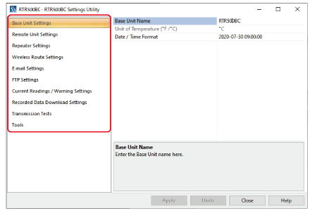
The Settings Utility Menu is as follows: For more details, click on any of the setting items below.
| MENU | Main Contents |
|---|---|
| Base Unit Settings | Base Unit Name and Date / Time Format |
| Remote Unit Settings | Registration to PC and Deletion, Properties (settings changes), Recording Start and Stop |
| Repeater Settings | Registration to PC and Deletion, Properties (settings changes) |
| Wireless Route Settings | Check Wireless Signal Strength and Make Wireless Route Settings |
| E-mail Settings | SMTP Name, Port Number, SMTP Authentication and so on |
| FTP Settings | IP Address, ID, Password, Port Number and so on |
| Current Readings / Warning Settings | Monitoring Settings, Current Readings Transmission Settings (Interval, Method, Storage), Warning Monitoring Settings (Monitoring Interval, Warning Transmission) |
| Auto-Download Settings | Download Scheduling Settings, Transmission Method, File Name, Storage Location and Save as Text File Settings |
| Transmission Tests | Transmission Tests for Current Readings, Warning Reports, and Recorded Data |
| Tools | Get Device Info, Initialize Devices (Remote Unit / Base Unit / Repeater) |
In order to carry out monitoring of Current Readings and Warnings it is necessary to have RTR500BC Data Viewer running on your PC. If the computer goes into sleep mode or the automatic update function of Windows is activated, Current Readings and Warning Info cannot be obtained, so make sure to check your PC settings in advance. (For details see: PC and Windows Settings)
| Base Unit Name | RTR500BC_Serial No. |
|---|---|
| Monitoring Current Readings | ON / Monitoring Interval: 10min. |
| Auto-Download | ON/ Send at 9:00 AM every day |
| Warning Monitoring | OFF |
Base Unit Settings
- Base Unit Name
-
Displayed as Model_Serial Number
When using multiple Base Units the name can be edited for easier identification.
Base Unit Names will be applied as follows:- E-mail for Warnings and Current Readings
- In Current Readings File Names and within the files themselves
- In Recorded Data File Names and within the files themselves
- Unit of Temperature (°F/°C)
-
Make settings for the unit of temperature to be used in the Remote Unit recorded data and in the display of the Remote Unit.
This cannot be changed after the Remote Unit has been registered. If you wish to change this setting, it is necessary to first delete the registration from the Base Unit and then make changes. - Date / Time Format
-
Select from one of the six available patterns.
This will be used everywhere except in data file names.
The RTR500BC does not have an internal clock. The recording date and time of the downloaded recorded data is calculated based on the PC clock. If your computer's clock is not correct, it will affect the recorded data.
Remote Unit Settings
- You can create up to 20 Groups of Wireless Routes per computer.
- Up to 32 Remote Units can be registered to each Group. (For RTR-574 and 576, registration of one unit will be counted as two units, so up to 16 units can be registered to each Group.)
Upon device registration/deletion or upon the start of a new recording session, all recorded data stored in the Remote Unit will be deleted. Make sure to download any recorded data you wish to save before making new recording settings.
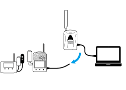
Communication at Remote Unit Registration and Deletion
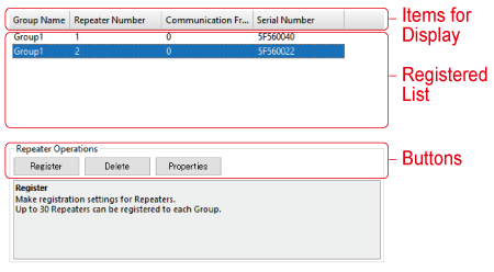
Settings Window
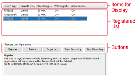
- Items for Display
-
Here you can change the items to be displayed and the order in which they are displayed.
- Right-click on the window and select [Display Item Settings] to make changes.
- Drag and drop the item left and right to change the order as desired.
- Registration List
-
This is a list of all Remote Units registered to the PC being used.
- [Register] Button
-
This opens the window that allows you to register data loggers to the PC as Remote Units.
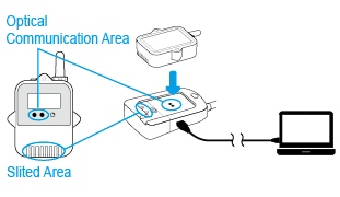
- If the data logger requires optical communication, connect the Base Unit with a USB cable to your PC and place the logger face down on the Base Unit.
- For RTR-574/576 loggers, connect directly to your PC with a USB cable.
- For RTR-600 loggers, connect the battery charge dock to your PC via USB and place the loggers on the charger.
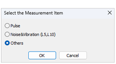
- If the Remote Unit is an RTR505B or RTR-505, a message box will appear for you to [Select the Measurement Item]. Click the suitable usage and click [OK] to open the settings screen. (This message will not appear if an Input Module is already connected.)
- [Delete] Button
-
Select the target Remote Unit from the registration list and click the button to open the "Delete Remote Unit" window.
When the Remote Unit is connected to a PC in the same way as during registration, the registration information in the Remote Unit will be deleted. When the process of deleting the registration information on the Base Unit is completed, the message "Success" is displayed and the targeted Remote Unit disappears from the list.- Recorded data will also be erased.
- If you are using the Shift/Ctrl key to select more than one Remote Unit, connect the next Remote Unit when [Initialized] is displayed for the currently connected device.
- If a Remote Unit cannot be connected to the PC because it is not at hand or is not working properly, select [Cancel] to delete the registration information in the Base Unit and finish the process. In this case, the registration information and recorded data will remain in the Remote Unit.
IMPORTANT
Unintended communication results may occur if a Remote Unit with registration information remaining in it is left within the radio communication area of a Base Unit for which communication is enabled. Make sure to initialize Remote Units from the [Tools] Menu. - [Properties] Button
-
Here Remote Unit settings changes can be carried out.
Select the target Remote Unit from the list and click the button.- In order to change an item that is grayed out, it is first necessary to delete the Remote Unit's registration information using the [Delete] button, initialize the unit and then re-register it.
- [Start Recording] Button
-
Here you can select a Remote Unit, make settings for the recording interval and the recording start date and time and start recording.
- If the set date and time for starting recording is too close to the current date and time, an error will occur.
- The Remote Unit will go into waiting mode and [REC] will blink in the Remote Unit LCD until recording begins.
- [Stop Recording] Button
-
Use this to select and stop recording in Remote Unit(s).
Setting Items
- Serial Number
-
This is the Remote Unit serial number.
- Group Name
-
This is the name of the Group to which the Remote Unit belongs. If you wish to register a logger to an already registered Group, select the name of the target Group.
- Groups can be created for each Wireless Route and up to 20 Groups can be registered.
- Remote Unit Name
-
Displayed as Model_Serial Number.
When using multiple Remote Units the name can be edited for easier identification.
Remote Unit Names will be applied as follows:- E-mail for Warnings and Current Readings
- In Current Readings File Names and within the files themselves
- In Recorded Data File Names and within the files themselves
- Remote Unit Number
-
The numbers are assigned automatically in order of registration.
- Communication Frequency Channel
-
Set a frequency channel for wireless communication to be used by Base Unit, (Repeaters), and Remote Units.
- Specify for each group to prevent interference during wireless communication.
- The frequency channels can be set from 0-21 for FCC Model and 0-11 for CE Model. For details see: FAQs - [RTR500BC Settings] - [Q. When there are multiple Base Units being used in the same area, what is the best way to assign frequency channels?].
- When more than one Base Unit is registered, make sure to select channels that are far apart in order to prevent interference of wireless communication between the Base Units.
- To make changes after having finished registration, it is necessary to delete all Remote Units and Repeater Units with the same frequency channel setting from the Registration List and then register them again.
- Ch.1, Ch.2
-
The measurement item for each channel is shown here.
- Recording Mode
-
Select the Remote Unit Recording Mode.
One Time: Recording automatically stops when the Remote Unit storage capacity becomes full.
Endless: Upon reaching logging capacity, the oldest data is overwritten and recording continues. - Recording Interval
-
Select from the 15 possible choices.
If the interval is changed, all recorded data stored in the Remote Unit will be deleted.
Below are some examples of recording intervals and maximum recording times.RTR501B/502B/
505BRTR503B/507B,RTR-574/576 Recording Interval 1 sec 4 hr and 26 min 2 hr 13 min 30 sec 5 days 13 hr 2 days 18 hr 15 min. 166 days 16 hr 83 days 8 hr 60 min. About 1 year and 10 months About 11 months - Warning Monitoring
-
Switch to ON to monitor for warnings, and set the "Warning Judgment Time". When a warning condition is detected, a warning is issued only after the judgment counter expires.
By setting to OFF, that unit will be excluded from monitoring for warnings.- Settings can be made in each channel for "Upper and/or Lower Limits". When an out-of-limit measurement is detected and continues for the set Judgment Time, a warning will be issued. (The set limit values are not sent with the warning message.)
- Additional Monitoring Items for RTR505B
Event: A warning will be issued when the rising or falling pulse continues for the set Warning Judgment Time. (resolution:1 sec)
Pulse: Settings can be made for upper and lower limits for pulse measurements taken during the set recording interval.
- Auto-Download
-
Select whether to enable automatic downloading of recorded data to the Base Unit.
- Auto-download / sending of recorded data will not occur for those Remote Units that are set to OFF.
Setting Items for RTR505B/RTR-505
- After making a setting, check the Remote Unit LCD to make sure everything is displayed correctly. (For details see: [RTR501B/502B/503B/505B/507B] - [RTR505B Display Examples by Input Module]).
- To replace an input module with another type, you must first delete the Remote Unit registration from the Base Unit, initialize the Remote Unit, and then register it with the new module.
Model number of input module shown within ( ).
- Sensor Type (TCM-3010, PTM-3010)
-
Select the type of sensor connected to the input module.
For TCM-3010: K, J, T, or S
For PTM-3010: Pt100 or Pt1000- When replacing a sensor with a different type, make sure to change this setting to reflect the type which is connected.
- Recording Method (VIM-3010, AIM-3010)
-
Make settings for the recording method for measurements.
Instantaneous Value: Records the instantaneous value measured at each recording interval.
Average Value: Records the average value of the measurements taken every second within the recording interval. - Scale Conversion Equation (VIM-3010, AIM-3010, PIC-3150)
-
Make settings for when using scale conversion. This has no reflection on what is displayed on the LCD display of the Remote Unit.
Use y=ax+b: Select this when the values for both the slope (a) and intercept (b) are already known.
Specify 2 points: Select this when both the input values from the sensor and the post-conversion values are known at two points. (See the sensor user’s manual for details)- If desired, a string of characters can be input directly to show the "Unit of Measurement" for the value after scale conversion.
- Preheat / Preheat Time (VIM-3010)
-
Select ON if you wish to control the sensor power supply. It transmits a preheat signal that is synchronized with the recording interval to turn sensors ON before and OFF after measuring and recording.
- Because the sensor does not measure except during a recording session, the Remote Unit LCD will refresh at each recording interval.
- The length of preheat time will differ upon your sensor. Please check the specifications for the sensor being used.
- If the set preheat time is equivalent to or longer than the recording interval, current will be continually supplied to the sensor.
- If this setting is changed, all recorded data stored in the Remote Unit will be deleted.
- Measurement Range (VIM-3010)
-
Make settings here for the range of measurement. The Remote Unit LCD will change to reflect the set measurement range.
V Range
Measurement Range: 0 to 22V
Resolution: Automatically changes from 0.1mV to 10mV according to the input signal.
Display Unit: V (fixed)
mV Range
Measurement Range: 0 to 999.9mV
Resolution: Automatically changes from 0.1mV to 0.4mV according to the input signal.
Display Unit: mV (fixed)- If this setting is changed, all recorded data stored in the Remote Unit will be deleted.
- LCD Display (PIC-3150)
-
Specify the value for display in the Remote Unit LCD.
Pulse Rate: The pulse count for recording interval period will be displayed. The display will be refreshed every one-sixtieth of the recording interval (at minimum of every one second).
Total Pulse Count: The pulse count (0 to 9999) since recording start will be displayed. The refresh interval is 1 second. - Pulse Signal Type (PIC-3150)
-
Make settings here for the pulse signal type to be recorded.
Rising: Records the number of rising pulses during the set recording interval.
Falling: Records falling pulses during the set recording interval.- If this setting is changed, all recorded data stored in the Remote Unit will be deleted.
- Chattering Filter (PIC-3150)
-
If you wish to use the filter for eliminating chattering which occurs due to changes in polarity, this should be switched to ON.
ON: 15Hz or less
OFF: 3.5kHz or less
(when using square wave signals of 0-3V or higher)- If this setting is changed, all recorded data stored in the Remote Unit will be deleted.
- Target Item for Warning Monitoring (PIC-3150)
-
Select the target item from Pulse or Event (rising or falling) and judgment time for warning monitoring.
Display resolutions for monitoring each target item are follows:
Pulse: one-sixtieth of recording interval (minimum of one second)
Event: 1 sec
- Noise & Vibration (L5, L10)
-
Make settings for the sampling interval, calculation percentage and calculation time period.
Setting Items for RTR-574/576
- Channels for Alternating Display (RTR-574)
-
Select the items to be displayed in the Remote Unit LCD.
- LCD Display Items (RTR-576)
-
Select the items to be displayed in the Remote Unit LCD.
- Button Lock
-
Use to lock the Remote Unit operation buttons. If set to ON, only the DISPLAY button will be functional.
- Note: When "Button Lock" is OFF and you change the recording interval using the INTERVAL button on the unit, that change will not be reflected to the Remote Unit information stored in the Base Unit. The change will be applied to the recorded data set.
- Atmospheric Pressure Correction (RTR-576)
-
Measurement results of CO2 concentration are affected by atmospheric pressure. This function corrects for atmospheric pressure to achieve a more reliable CO2 concentration measurement.
This setting can be made by directly entering the pressure (hPa) at the measurement location, or by having the software calculate the estimated pressure at the altitude (meters) entered by the user. - Auto Calibration (RTR-576)
-
It is possible to calibrate the CO2 sensor either automatically or manually.
Refer to Calibration / Adjustment Function for the operation procedures and precautions.
Repeater Settings
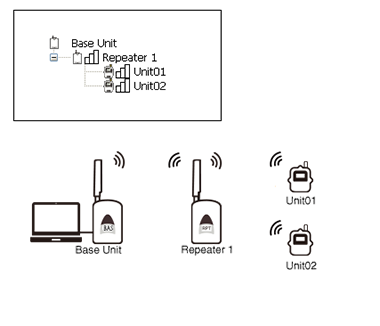
The wireless communication range can be extended by placing a Repeater in between a Base Unit and a Remote Unit.
- The wireless communication range, if unobstructed and direct, is about 150 meters (500ft).
- You can create routes for up to 20 groups per PC, and you can register up to 30 Repeaters in each group.
- After adding or deleting a Repeater, go to Wireless Route Settings and carry out a radio signal strength test.
- Items for Display
-
Here you can change the items to be displayed and the order in which they are displayed.
- Right-click on the window and select [Display Item Settings] to make changes.
- Drag and drop the item left and right to change the order as desired.
- Registration List
-
This is a list of all Repeaters registered to the PC being used.
- [Register] Button
-
This opens the window that allows you to register devices to the PC as Repeaters.
- [Delete] Button
-
Select the target Repeater from the registration list and click the button to open the "Delete Repeater" window.
When the Repeater is connected to a PC in the same way as during registration, the registration information in the Repeater will be deleted. When the process of deleting the registration information on the Base Unit is completed, the message "Success" is displayed and the targeted Unit disappears from the list.- If you are using the Shift/Ctrl key to select more than one Repeater, connect the next Repeater when [Initialized] is displayed for the currently connected device.
- If a Repeater cannot be connected to the PC because it is not at hand or is not working properly, select [Cancel] to delete the registration information in the Base Unit and finish the process. In this case, the registration information and recorded data will remain in the Repeater.
IMPORTANT
Unintended communication results may occur if a Repeater with registration information remaining in it is left within the radio communication area of a Base Unit for which communication is enabled. Make sure to initialize Repeaters from the [Tools] Menu. - [Properties] Button
-
Here Repeater settings changes can be carried out.
Select the target Repeater from the list and click the button.- In order to change an item that is grayed out, it is first necessary to delete the Repeater's registration information using the [Delete] button, initialize the unit and then re-register it.
Setting Items
- Serial Number
-
This shows the Repeater serial number.
- Group Name
-
Specify the Group to which the Remote Units are registered that you wish to add a Repeater.
- Repeater Number
-
The numbers are assigned automatically in order of registration.
- Communication Frequency Channel
-
Set the frequency channel for Repeater to the same one as the Remote Unit to which you wish to communicate.
- Specify for each group to prevent interference during wireless communication.
- The frequency channels can be set from 0-21 for FCC Model and 0-11 for CE Model. For details see: FAQs - [RTR500BC Settings] - [Q. When there are multiple Base Units being used in the same area, what is the best way to assign frequency channels?].
- When more than one Base Unit is registered, make sure to select channels that are far apart in order to prevent interference of wireless communication between Base Units.
- To make changes after having finished registering, it is necessary to delete all Remote Units and Repeater Units with the same frequency channel setting from the Remote Unit Registration List and then register them again.
Wireless Route Settings
Make wireless route settings here for communication between Base Units, Repeaters and Remote Units and carry out tests of signal strength between the various devices.
- The wireless communication range, if unobstructed and direct, is about 150 meters (500ft).
- For more info about installation see: [Please Read First] - [About Installing Wireless Communication Devices] in this Help.
- Anytime you decide the installation points, add or delete devices, or communication errors continually occur, it is a good idea to make sure communication is stable and reliable by testing the signal strength of wireless communication between the Base Units, Repeaters and Remote Units.
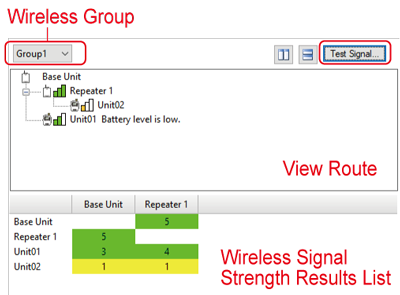
- Wireless Group
-
Select the wireless group of which you wish to view communication routes or test signal strength.
- [Test Signal] Button
-
After having specified the desired Group, click the button.
In the [Check Wireless Signal Strength] window, select the device and start the test. Close the window when communication is completed. - View Route
-
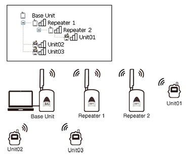
The wireless route for the group selected from the Wireless Group list can be viewed here and changes can be made to the route.
- The signal strength is show in colored bars. Two or more green bars is ideal.
- A message will be displayed when Remote Unit battery power becomes low.
- To create or change a route, drag and drop Remote Unit and Repeater icons to the desired position within the wireless route where you would like them to be and click the [Apply] button.
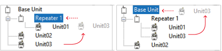
Left Figure: If you wish to move [Remote Unit Refrigerator 1] under the [Repeater 1] tree, drag the icon up into the Repeater 1 icon.
Right Figure: If you wish to move [Remote Unit Refrigerator 1] to directly connect with the Base Unit, drag the icon from the Repeater tree up into the Base Unit icon.
- Wireless Signal Strength Results List
-
The signal strength results for the selected Wireless Group's Base Unit, Repeaters and Remote Units are displayed in both colors and numerical values.
Green (3-5): Good
Yellow (1-2): Unstable
White (0): Error
- The frequency channel cannot be moved between groups.
- After completing settings, deploy the device to its location and check the signal strength.
E-mail Settings
Make settings here when sending the current readings, recorded data, and warning info to your e-mail server.
- SMTP Server
-
Enter the outgoing mail server (SMTP server) name.
EX: smtp.example.tandd.com - SMTP Port Number
-
Enter the SMTP server port number.
- Sender
-
Enter the e-mail address of the Sender to be displayed in the received Warning Report Mail.
- It should be noted that if you assign an imaginary address, in some cases the SMTP server will judge the mail to be SPAM or junk mail and not allow it to be sent. Make sure to enter a domain that actually exists.
- SMTP Authentication
-
If you wish to use "SMTP" authentication for authentication when sending email, switch to ON and enter your User ID and Password.
- Compatible authentication methods are LOGIN / PLAIN / CRAM-MD5
- Connection Security
-
Select an encryption method (Auto / STARTTLS / SMTPS (SMTP over SSL/TLS)) for email transmissions.
- TLS 1.2 is supported.
FTP Settings
Make settings here when sending current readings and recorded data to T&D WebStorage Service or to your own FTP server.
- FTP Server
-
Enter the "IP Address" or "Host Name" for your FTP Server.
If you wish to use T&D WebStorage Service, please enter ftp.webstorage-service.com. - FTP User ID
-
If you wish to use T&D WebStorage Service, please enter the User ID you received upon User Registration.
- FTP Password
-
If you wish to use T&D WebStorage Service, please enter the Password you received upon User Registration.
- FTP Port Number
-
If you wish to use T&D WebStorage Service, please enter [21].
- Passive Mode
-
Select whether to use Passive Mode or not.
If you wish to use T&D WebStorage Service, switch to ON.
Current Readings / Warning Monitoring Settings
Here you can make settings for using RTR500BC Data Viewer for monitoring current readings and warnings.
- Monitoring Current Readings
-
If you wish to monitor current readings, switch to ON.
- If either [Send Current Readings] or [Warning Monitoring] is switched to ON, this function is automatically ON.
- Monitoring Interval
-
Select from the 11 choices for gathering current readings.
- This interval is automatically changed when changes are made to either the [Sending Interval] or the [Warning Monitoring Interval].
- Auto Transmission of Current Readings
-
Set to ON to have current readings sent automatically.
- Transmission Interval
-
Select from the 11 choices (1, 5, 10, 20, 30min, 1, 2, 4, 6, 12, 24 hours) for transmitting current readings.
- Please make the sending interval longer than that of the Remote Unit recording interval setting. (If the recording interval is 10 minutes, set to a value higher than 10 minutes.)
- Transmission Method
-
Select the transmission method for sending current readings.
Select "FTP" or "Email".- If you wish to send data to T&D WebStorage Service, please select FTP and leave the Destination Folder blank.
- Saving Current Readings Data
-
When incorporating into a system or application developed by the customer and linking to that system, switch to ON.
- File Name
-
If you specify the file name that does not contain time, the file will be overwritten.
EX: If you select <base>_<time>, the file name will be [Base Unit Name_Date/Time]. - Warning Monitoring
-
Switch to ON to monitor for warnings.
- Warning Monitoring will not be carried for those Remote Units which have Warning Monitoring set to OFF in the Remote Unit Settings.
- Warning Monitoring Interval
-
Select the interval (1 or 5 minutes) for monitoring for warnings.
- Warning Transmission
-
If you wish to have warning reports sent by e-mail, switch to "ON".
- If you switch to ON, select [E-mail Settings], and make the necessary settings for sending e-mail.
- Warning Recipients 1-4
-
Up to four e-mail addresses can be entered.
- Use the pull down menu to specify the conditions for sending a warning report mail to the specified recipient's address.
- Subject
-
Enter a subject for the warning report mail.
- Comments
-
This will be the body of the warning report e-mail.
You can enter up to 64 characters. (Optional)
Recorded Data Download Settings
Make settings here to automatically download recorded data.
- Auto-Download
-
Select whether to automatically download recorded data.
- Auto-downloading will not be carried for those Remote Units which have Auto Download set to OFF in Remote Unit Settings.
- Auto-Download Schedules 1-8
-
Settings for up to 8 auto-download patterns can be selected.
- If you select more than one date and time, make sure that they are one or more hour apart.
- Transmission Method
-
The downloaded recorded data can be sent via e-mail or FTP.
If you only need to save the downloaded file to your PC, select [Do not send].- If you wish to send by e-mail, enter the recipient e-mail address and the subject of the mail.
- When sending by FTP, enter the address of the destination folder.
- If you wish to send data to T&D WebStorage Service, please select FTP and leave the destination folder blank.
- File Name
-
Specify the file name for the file to be sent or saved.
EX: If you select <base>_<remote>_<time> the file name will be [Base Unit Name_Remote Unit Name_Date/Time].- If you specify a file name that does not contain time, the file will be overwritten.
- Data File Format
-
Specify the file format from [T&D File Format] or [XML File Format (publicized)] for sending or saving data.
- Both formats can be used by T&D Graph for data analysis.
- If you wish to use the data with one of our older graph tools (Temperature / Humidity Graph or Multi-Scale Graph), please specify [T&D File Format].
- When the destination for the recorded data is T&D WebStorage Service, please specify [XML File Format (publicized)].
- When incorporating into a system or application developed by the customer and linking to that system, please specify [XML File Format (publicized)].
- Saving Recorded Data
-
If you wish to save the recorded data to your PC, switch to ON.
- Storage Folder for Recorded Data
-
Specify the folder in which to save the recorded data.
- Save as Text File
-
If you wish to create a text format file that can be read by spreadsheet software, switch this to ON and specify the destination folder and delimiter.
Transmission Tests
Carry out any of the necessary tests from the [Transmission Tests] Menu.
If a test fails, see the explanation and error codes and make settings changes as necessary. (For details see: Error Code List)
- In order to carry out these tests it is necessary that the PC to which the Base Unit is connected be properly connected to a network and that communication with the E-mail Server and/or the FTP server has been established.
- In the transmission test window, any improperly made settings or unmade settings will appear in red.
- The test data cannot be viewed in graph form.
Tools
Here you can get and view device information and initialize devices.
- Get Remote Unit Info
-
This will show info for the Remote Unit connected to your PC.
- Initialize Remote Unit
-
This returns the Remote Unit to its original factory default settings. (See: [Notes on Initializing Remote Unit/Repeater])
- Get Base Unit (Repeater) Info
-
This shows the Base or Repeater Info for the device which is connected via USB to the PC.
When running on batteries, the battery level will be displayed in levels from 0 to 5.
3-5: OK
1-2: Change batteries (Communication errors may occur.)
0: No battery power (Communication will be interrupted which may cause loss of recorded data.) - Initialize Base Unit (Repeater)
-
This returns the Base Unit (Repeater) which is connected by USB cable to the PC to its factory default settings. (See: [Notes on Initializing Remote Unit/Repeater])
Notes on Initializing Remote Unit/Repeater
- After initializing a Remote Unit or Repeater, make sure to delete it from the registration list in Remote Unit Settings or Repeater Settings. Failure to do so may cause a communication error or operation error.
- Once initialized, the setting information and recorded data in the unit will be deleted and cannot be restored.
- When initializing the Remote Unit that uses a High Precision Temp-Humidity Sensor SHA-3151, SHB-3101, Thermocouple Module TCM-3010, Pt Module PTM-3010, 4-20mA Module AIM-3010, or Voltage Module VIM-3010, if you were making adjustments to the measurements (via Adjustment Tools), the setting has been saved in the sensor/module and will remain even if the Remote Unit is initialized. To reset the adjustment setting, use the Adjustment Tools software and perform the initialization.
PC and Windows Settings
In order to carry out Auto-Download of Recorded Data and Warning Monitoring, it is necessary to have RTR500BC Data Viewer running on your PC.
If the computer goes into sleep mode or the automatic update function of Windows is activated, Auto-Download of Recorded Data and Warning Monitoring cannot be carried out.
Disable the sleep function on your PC
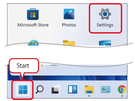
Windows 11
-
Click [Settings] in the Start Menu.
-
Click on [Power] (or [Power & battery]).

-
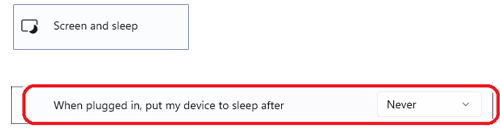
Click on [Screen and sleep], and select [Never] from the [When plugged in, put my device to sleep after] drop-down menu.
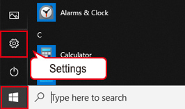
Windows 10
-
Click [Start] and then click [Settings].
-
Click [System].
-
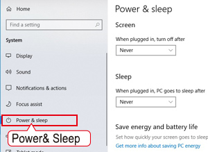
Click on [Power & sleep] and select "Never" for when to turn off the screen and when to enter sleep mode.
Managing Windows Update Settings
Make settings to avoid unexpected automatic system shutdown due to Windows Update on the PC on which RTR500BC for Windows is running.
- This is information as of March 2022. Due to changes in Windows specifications, descriptions and images may differ from the actual screen.
- For companies and organizations that have established an information security policy or have implemented WSUS (Windows Server Update Services), please check with your network administrator before making these settings.
| Proposed Methods | Home Edition | Pro Edition | Description |
|---|---|---|---|
| Enable notification only and update later | − | Only notifies about the update and applies Windows Update later at user discretion. This method uses Group Policy Editor and works only with the Pro Edition. > Setting Procedure | |
| Set active hours | Set the time when you don't want the system to be restarted. This is the suggested method when it is difficult to use the Group Policy Editor, such as when using the Home Edition. > Setting Procedure | ||
| Use in offline environment | Windows Update will not run in an environment without an Internet connection. |
Enabling the Update Notification
When there is an update available, only a notification will appear. You will need to download and install it later.
-
Type "gpedit.msc" in the search box on the Windows Start menu and press Enter to open the [Local Group Policy Editor].
-
Go to [Computer Configuration] - [Administrative Template] - [Windows Component] - [Windows Update]. There will be several policies on the right-hand pane; double click on the [Configure Automatic Update] policy to access it.
-
Check [Enable] and under Options: Configure automatic updating, select [2-Notify for download and auto install], then click the OK button.
Configuring Active Hours
After the computer restarts, you need to log in and start the T&D Data Server.
-
Open [Settings] from the right-click menu on the Windows Start Menu button.
-
Click [Update & Security].
-
Go to [Change Active Hours] in Windows Update.

-
Click [Change] to open the Active hours screen. Set the Start time and End time during which you don’t want the system to restart, then click the Save button.
Setting Example: Computer will not restart between 8:00 and 23:00
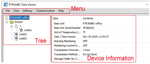
RTR500BC Data Viewer
While RTR500BC Data Viewer is running, you can monitor current readings, monitor for warnings, automatically download recorded data, etc.
When you open the Data Viewer, you will see the device tree and device information as shown below.
| MENU | Contents | ||
|---|---|---|---|
| File | RTR500BC Settings Utility | This will open the Settings Utility. (For details see: Software Operational Settings) |
|
| Exit * | *Do NOT click exit if you want to continually monitor for current readings and warnings. If the computer goes into sleep mode or the automatic update function of Windows is activated, Current Readings and Warnings cannot be received. (For details see: PC and Windows Settings) |
||
| View | View Auto Download Schedule | The time of the next scheduled Auto-Download will appear here for each Remote Unit. | |
| View Log | Here you can view the auto-download and warning logs, as well as, save them or output them as text file. Once a month the text file data will automatically be exported and saved to specified folder. (For details see: View Log) |
||
| Monitor Current Readings | This opens the [Monitor Current Readings] window. (For details see: Monitor Current Readings) |
||
| Storing to Task Tray | By storing this in the task tray, you can prevent the accidental quitting of the application. (For details see: Store in Task Tray) |
||
| Expand to Whole Tree | This will open the entire tree. | ||
| Show Dialog during Auto Download | Remove the check if this is not necessary. | ||
| Show Dialog during Monitoring of Current Readings | Remove the check if this is not necessary. | ||
| Settings | Settings for Monitoring Current Readings | Graph Settings | Here you can edit the graph, scale lines, background color and display period shown when monitoring Current Readings. |
| Selection of Remote Units for Display | Here it is possible to select which Remote Unit data is to be displayed and hidden when monitoring Current Readings. Even though the data for Remote Units is not displayed in the Current Readings Monitoring Window, that data is being collected and warning monitoring for those units is also being carried out. | ||
| Pause Polling | "Polling" is when the Base Unit periodically communicates via wireless communication with Remote Units to automatically download recorded data, monitor current readings and warning signals at regular intervals. If the number of Remote Units and/or Repeaters is quite large and the amount of time it takes to carry out this communication is too long, or if you wish to make settings changes or carry out some other process without the periodic communication interfering, it is possible to pause this polling. | ||
| Audible Alarm Settings | Check here to have an alarm notification sound from your PC speaker when a warning occurs. You can choose to select a sound file as the alarm notification sound by checking [Select audio file (wav)] and specifying the desired file. | ||
| Communication | Download Data (Wireless) | Select the target Remote Unit(s) from the tree and download the data by wireless communication. (For details see: [Communication] Menu) |
|
| Download Data (Optical Communication) | Use this to download recorded data from RTR501B, 502B, 503B, 505B, and 507B units. (For details see: [Communication] Menu) |
||
| Download Data (USB Communication) | Use this to download recorded data from RTR-574 and 576 units. (For details see: [Communication] Menu) |
||
| Gather Current Readings | This will gather Current Readings from Remote Units and start monitoring. | ||
| Help | Help | Opens this Help | |
| Version Info | This will display the version info for the RTR500BC Data Viewer being used. | ||
View Log
Here you can check up to 3000 Auto-Download logs and 3000 Warning logs.
When the number exceeds 3000 records, the oldest will be automatically deleted and the newest one saved; if necessary please periodically use "Save Log as Text File" to save important data.
Exporting to Text File and Clearing Logs
Click the [Output as Text] button and make detailed settings for exporting and saving the text files.
Click the [Clear Log] button to delete the log from the file and refresh the display.
Settings for Auto Output of Logs in Text File
Use this to automatically export text files and save them to a specified folder.
- The "Data Format" and "Delimiter" used will be the same as selected in [Output as Text] above.
- File names cannot be assigned. File names, including the output date, will be as follows:
Auto-Download Log: log_autodl_2020_07(Jul).txt
Warning Log: log_warning_2020_07(Jul).txt
Monitor Current Readings
This gathers current readings and refreshes the graph at the interval specified in Settings Utility - [Current Readings / Warning Monitoring Settings].
In addition to the graph, the next scheduled time for getting readings, the refresh interval, and Remote Unit Info (Remote Unit Name, Current Reading, Time of Last Communication, and Battery Level (BAT: 0 to 5) are displayed.
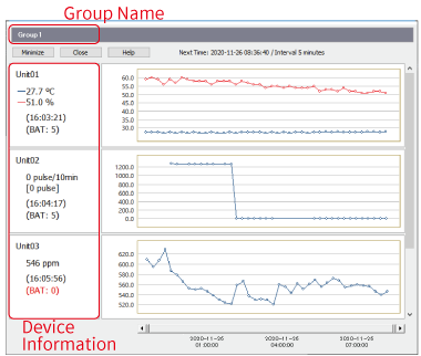
- If the battery level is [BAT: 2], please change the batteries as soon as possible. If the level reaches [BAT: 1] or below, communication errors and loss of data may occur.
- Since RTR-574 and RTR-576 Remote Units are multi-channel units they use multiple graph areas, therefore it may not be possible to display all Remote Units in the Group.
Store in Task Tray
When opening and working in many screens on your PC, you can store the application screen to the task tray to prevent accidental quitting of the application.
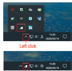
- The task tray is the notification area at the bottom right of your computer screen.
- Click the application icon to display its screen.
- If the icon is hidden, left click the arrow icon (∧) to display the applications.
[Communication] Menu
When you immediately want to get Recorded Data, you can download it by wireless communication and save the data to your PC.
Connect the target Remote Unit(s) to your computer (optical communication or USB communication) and download one by one.
After the data has been downloaded, the date and time of the recorded data are reverse calculated from your computer's clock. If your computer's clock is not correct, it will affect the time stamp of the recorded data.
Downloading Method
Select the range of data you wish to download.
- Download All Data
-
This will download all recorded data in the Remote Unit. One logger at full data capacity will take about 2-3 minutes to download to a PC. If there are any Repeaters the communication time will increase.
- Specify Time
-
Period Download only data from the set number of hours before until the most recently recorded data. Entries can be made in units of 1 hour.
If no name is assigned or specified, the data will be saved in the file name and destination folder that was set in the Settings Utility.
Checking and Updating the Firmware Version
By opening the [Tools] menu in the Settings Utility you can check the firmware version of the device connected to the PC via USB.
In the launcher window click [Update Information] to open the Check for Updates Tool*
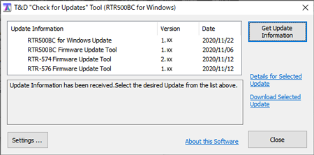
* This will automatically notify you of the latest information on related software and update programs.
During a firmware update, monitoring for current readings and warnings and well as data collection cannot be executed.
- Update Information
-
This shows program versions and date of update.
- [Settings] Button
-
Here you can select whether or not to automatically check for the latest software version information on the Internet when the Setting Utility is started.
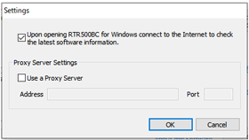
- If you wish to use a proxy server to check and update the firmware, check [Use a Proxy Server] and enter the IP address and port number.
- [Get Update Information] Button
-
Use this to get the settings info for the Last Page.
- [Details for Selected Update]
-
Clicking here will take you to T&D Website > News > Update Info where you can view details for the program that you selected.
- [Download Selected Update]
-
Clicking here will take you to T&D Website > Software Download where you can download the update for the program that you selected. Precautions and update procedure info is also available here.
Error Code List
This is an error code list explaining various common error codes that may appear while using the RTR500BC Settings Utility.
If an error message appears that is not in the below list, make a note of the error and please contact your local Distributor.
| Communication | Error Code | Problem | Probable Cause and Solution |
|---|---|---|---|
| Wireless Communication | 40001 | Wireless Communication Busy | Another wireless communication session is being processed. Please wait and try again. |
| 40002 | Wireless communication failed. (Remote Unit) | Please try initializing and re-registering the Remote Unit. | |
| 40003 | Wireless Communication was canceled | Change the position(s) of the Base Unit, Repeater(s), and /or the Remote Unit(s) and try again. Make sure that there is sufficient battery power in the target Remote Unit(s) and Repeater(s). |
|
| 40004 | Wireless Communication Failure (Repeater) | Check conditions (such as the signal strength and battery status) of the Repeater to make sure wireless communication can be carried out. | |
| 40005 | Wireless Communication Failure (Remote Unit) | Check conditions (such as the signal strength and battery status) of the Remote Unit to make sure wireless communication can be carried out. | |
| 40006 | Wireless Communication Failure (Repeater) | Check conditions (such as the signal strength and battery status) of the Repeater to make sure wireless communication can be carried out. | |
| 40007 | Recording cannot begin because there are not enough seconds remaining before the scheduled Recording Start. | The amount of time before the set recording start date and time is too short. Please change the date and time for the recording start and try again. | |
| 40021 | Wireless communication channel is unavailable (channel busy). | Channel is busy. Move the device as far away as possible from noise emitting devices such as PCs. | |
| Optical Communication: | 50001 | No Response from the Remote Unit | Make sure that the Remote Unit is face down and that the optical communication areas are aligned properly. |
| Bluetooth Communication | 80001 | Command rejected by Bluetooth communication | Make sure you have a Bluetooth connection and that your passcode is correct. |