RTR-600
Introduction
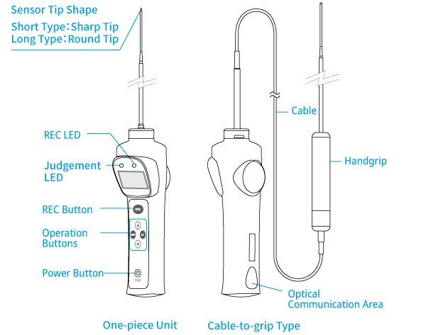
Our RTR-600 Series food core temperature loggers are both waterproof and oil resistant.
RTR-600 is available for US only.
Here is a description of the device. For the settings, refer to the table below [References for Compatible Base Units and Settings].
| RTR500BW (Discontinued: RTR-500NW/500AW) |
[RTR500BW + RTR-600 Setup Guide](PDF) | |
|---|---|---|
| RTR500BC, RTR-500 (*) | [RTR500BC for Windows] section of this Help | |
| * Customers wishing to use the RTR500BC or RTR-500 as a Base Unit, please contact your local distributor for the communications protocol specifications to write your own software. | ||
Included: Manual Set (Warranty Included)
This product contains recyclable Ni-MH batteries.
| Sensor Materials | |
|---|---|
| Sensor | Stainless Steel (SUS316) |
| Handgrip | Flame-retardant PPE/PA6 Temperature Durability: About 170 °C |
| Cable | Fluoropolymer Coated Electrical Wire Cable Length: 900 ㎜ |
To Prevent Serious Accidents
Do not use this product in ways other than its intended purpose.
- This product has been designed to measure the temperature of food and liquids.
- Do not use it for any purpose other than for which it was designed. Because the sensor has a sharp tip, there is a risk of accidentally stabbing people and/or objects. Do not use the sensor for any purpose other than measuring the temperature of objects for which it was designed.
Place and store in a safe place.
- Avoid placing the unit in unstable areas exposed to vibration, slippery surfaces, or within reach of small children.
- When not in use, put a cover on the sensor tip and store in a safe place.
Clean and sterilize units before and after use.
- If a unit gets dirty or oily, wipe it with a clean cloth dipped in alcohol.
- NEVER use an acid, alkaline, or chlorine based detergent. This will cause harm to the electric components in the unit or the battery charge dock.
Do not touch sensor immediately after measurement.
- Please be careful when using in extreme hot or cold environments; touching the unit may cause burns or frostbite.
Other Precautions
- Do not disassemble, repair or modify the unit and/or accessories.
- Do not forcibly insert the sensor into hard objects such as frozen food. It may cause to sensor breakage, leading to unexpected accidents and injury.
- Do not cut or process the sensor cables. Also, do not twist, pull or swing any of the cables.
- We are not responsible for any damage, malfunction or trouble, whether direct or indirect, caused by the use of our product.
- To prevent damage to the unit from static electricity, remove static electricity from your body before touching the unit.
- Do not shield the communication area with a tape as it may cause communication errors.
Button Operation and Reading the LCD Display
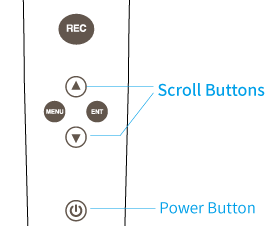
- [REC] Button
-
When this button is pressed, the Temperature, Date, Time, User Name, Item, and Judgement Result at the time of pressing are recorded into the unit.
The REC LED and the judgement LED also both go ON.
(For details see: Details about the LED Light) - Power Button
-
Press to turn the power ON or OFF.
The automatic power-off function automatically turns off the power after about five minutes of inactivity. - [MENU] Button
-
By pressing this button, the menu will be displayed. Also, press to return to the previous screen.
- [ENT] Button
-
Press to enter the settings menu or confirm a setting.
- Scroll Buttons
-
Press to move the arrow cursor up and down or scroll the screen. (For details see: Main Menu Screen)
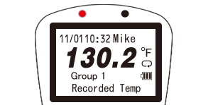
Top Screen
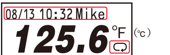

Current Date (MM/DD), Time (HH:MM), and User Name
When the REC button is pressed, this information is recorded into the unit.
- A maximum of 8 characters can be displayed for a user name.

Recording Mode
Endless Mode (fixed): Upon reaching logging capacity of 1,800 readings, the oldest data is overwritten and recording continues.

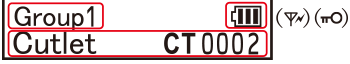
Work Group Name
A maximum of 8 characters can be displayed as a work group name.
Icons
Icons will be displayed according to the situation.
Battery Level: When the battery is too low to measure temperature, the "Please charge batteries" message will appear.
Communication Antenna: This icon appears during wireless communication with the Base Unit.
Button Lock: This icon appears when "Button Lock" is set to ON in the software. Button operation will be OFF for all buttons except for the REC and Power buttons.

Measured Item and Count No.
The item being measured and a count number to show how many times this item has been measured are shown here.
- The count number will be reset to zero every time a Work Group Table is sent to the RTR-600 via software.
- A maximum of 12 characters can be displayed for a measured item.
- The above screen shows the temperature of a cutlet that has been measured two times.
- Please set the internal clock of the device in the RTR-600 Settings Utility - [Remote Unit Settings] - [Clock Settings].
- Settings for the user name, work group name, and measured item can be made when creating a [User Table] or [Item Table] with RTR-600 Settings Utility.
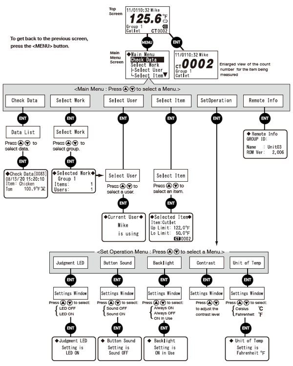
Main Menu Screen
By pressing the MENU button, the Main Menu will appear as shown below.
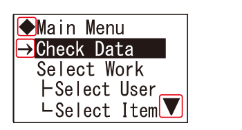

Menu Name
Icon that appears next to the menu name.
Cursor
The item selected with the cursor will be highlighted.
Move the cursor with the scroll button on the device to select a menu or data.
(For details see: Button Operation and Reading the LCD Display)
Scroll Arrows
These indicate that there are more menu items above or below.
Use the scroll buttons on the device to move up and down.
(For details see: Button Operation and Reading the LCD Display)
Menu Contents
The following operations and settings can be made from the device itself.
If you see the Button Lock icon (![]() ) in the top screen, the button operation on the device will be restricted; please use the RTR-600 Settings Utility – [Remote Unit Settings] – [Properties] window to change the settings.
) in the top screen, the button operation on the device will be restricted; please use the RTR-600 Settings Utility – [Remote Unit Settings] – [Properties] window to change the settings.
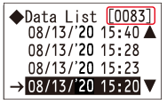
Data List
By selecting the [Check Data] menu, all recorded data in the Remote Unit is displayed in a list in descending order (from newest to oldest data).
- The sample screen shows the 83rd data reading highlighted by the cursor.
- Select data by moving the cursor and press the ENT button to view detailed information.
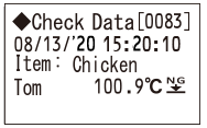
Check Data
Check details of the selected data: date (mm/dd/yy) and time (hh:mm:ss) of recorded data, measured item, user name, measurement, and judgement result.
![]() Judgement OK
Judgement OK
![]() Upper Limit Error /
Upper Limit Error / ![]() Lower Limit Error
Lower Limit Error
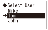
Select User / Select Item
Here you can select the User and the Item.
- If you have registered Work Groups, it is also possible to select from the [Select Work] menu.
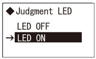
Judgement LED
By setting to "LED ON", the Judgement LED will blink when a measurement exceeds the set upper or lower limit.
(For details see: Judgement LED (red or green))
- This can also be done from the software RTR-600 Settings Utility.
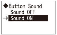
Button Sound
Turn ON or OFF the beep which sounds when a button is pressed.
- This can also be done from the software RTR-600 Settings Utility.
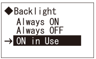
Backlight
The [ON in Use] option will backlight the display for three seconds only during operation.
- This can also be done from the software RTR-600 Settings Utility.
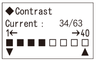
Contrast
Use the cursor buttons to adjust the contrast of the display.
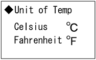
Unit of Temp
Select Celsius [°C] or Fahrenheit [°F].
- This can also be done from the software RTR-600 Settings Utility.
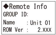
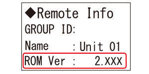
Remote Info
The Group ID, Remote Unit Name and Firmware Version can be viewed here for the unit being used.
(For details see: Checking and Updating the Firmware Version)
- The Group ID is automatically assigned upon registering a Remote Unit.
Message Display
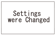
Settings were Changed
When Remote Unit setting changes are received from the Windows software, this is displayed for about 2 seconds and then returns to the top screen.
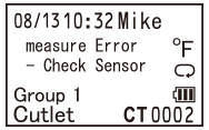
Sensor Error
Please contact your local distributor if you see this message.
Operations Table
Details about the LED Light
REC LED (orange)
- On (Normally)
-
Upon pressing the REC button this lamp will come on.
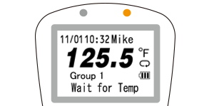
After about three seconds, the orange LED turns off and the display automatically returns to the top screen. - Blinking (Wait for Temp)
-
After having pressed the REC button, do not remove the sensor from an object being measured while "Wait for Temp" is on display and the orange LED is blinking.
- When the "Wait for Constant Temp Settings" has been set to ON in the software and temperature is not stable, the orange LED blinks meaning a recording is pending.
- If the temperature is not stabilized even after 15 seconds have elapsed, recording will not be performed and you will be returned to the top screen.
Judgement LED (Red / Green)
By setting to "LED ON", the Judgement LED will blink when a measurement exceeds the set upper or lower limit.
- Blinking (green)
-
The measurement is within the set limits.
- Blinking (red)
-
The measurement has exceeded one of the set limits.
Settings for the upper and lower limits can be made when creating an [Item Table] with RTR-600 Settings Utility.
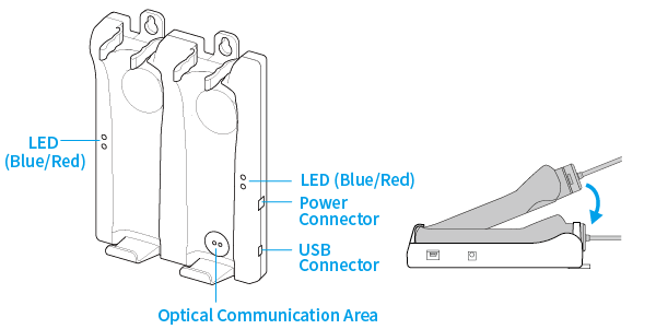
Battery Charge Dock
A battery charge dock RTR-600BD (sold separately) is required to use the functions of RTR-600 series loggers.
Included: AC Adaptor AD-05A3, USB Cable US-15C, Wall Mount Screws ×3, Manual Set (Warranty Included)
Use for Remote Unit Registration
The battery charge dock can be used as a USB interface for registering Remote Units via the software. Connect the RTR-600BD to a PC with the supplied USB communication cable and place the target RTR-600 onto the side with an optical communication area.
Use as a Battery Charger
Two loggers can be charged simultaneously.
Connect to the power supply using the supplied AC adaptor and place the loggers on the battery charge dock.
While charging the LED on the dock will appear blue and the green LED on the logger will be ON. Upon completion both lamps will turn OFF.
Please stop using in the following situations:
Battery Charge Dock: If the red LED turns ON
- If the dock recognizes an irregular electrical activity, it automatically stops charging and the red LED will light up. Unplug the dock and check if there is any foreign matter caught between the battery charge dock and the device.
- The red LED on the dock may light up for just a moment due to power fluctuation. There is no problem unless the red LED remains on.
- If, after checking the above and resetting the unit several times, the red LED on the dock remains on, please stop using the dock and contact your distributor.
Data Logger: If the orange LED is BLINKING
- If the body of the unit gets too hot (over 40 °C), the orange LED will start blinking and battery charging will temporarily stop. Once the body cools down, charging will restart.
Handling Precautions
- Before placing a logger on the battery charge dock, make sure it is wiped clean.
- Do not dirty or block any part of the optical communication area of the battery charge dock. This may cause communication errors.
- Note that it is not possible to take measurements or make settings while the logger is charging on the dock. Please stop charging if you wish to take measurements.
Measurement Adjustment Function
By using Adjustment Tools, it is possible to adjust the readings measured by Remote Units.
Adjustment for differences will be carried out using an adjustment equation of y=ax+b; where x is the pre-adjusted reading (Current Reading) and y is the post-adjusted reading.
- 1 Point Adjustment
- Use this to adjust all measurements with the same offset. (The whole graph will be adjusted up or down, keeping the same slope.)
- 2 Point Adjustment
- Use this to adjust measurements in a wide range or when adjustment cannot be carried out using only one point. (The slope will change.)
T&D Website > Software/Apps > Adjustment Tools
- We cannot guarantee that after carrying out adjustment of the measurement, accuracy will improve for all measuring ranges.
- When making adjustments to Illuminance and UV Intensity, it is recommended to use a point closest to "zero" for adjustment.
- Adjustment function is set in the sensor, and the settings will remain even if the Remote Unit is initialized. To initialize the adjustment settings, use the Adjustment Tools.
- When a sensor is replaced, it is necessary to re-make any desired adjustment settings before using the new sensor.
- If you want to make adjustments to a sensor that has already been adjusted, initialize the setting first.
Device Initialization
To initialize a logger please use the software for the model of Base Unit to which it is registered.
For details about operation, see the following sections of this Help.
- [RTR500BW for Windows] - [Settings Utility Main Window] - [Operations] Menu
- [RTR500BC for Windows] - [Base Unit Settings] - [Tools]
Checking and Updating the Firmware Version
The firmware version of the device can be found by opening [Remote Unit Info] in the Main Menu.
Details about version updates and procedures can be found on the software download page; please check the details when downloading.
T&D Website > Software/Apps > RTR-601/602 Firmware Update Tool