Device Settings
How to Reset ALM/Max/Min Display (A2/A)
Clear ALM Display
For the TR7A2/A with upper/lower limit and/or sensor warning enabled in the Warning Settings, the [ALM] icon will flash on the LCD screen when a warning is detected.
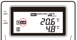
Normally, the [ALM] icon will automatically disappear when the warning condition is resolved. However, when the device in Vaccine Mode* has an upper or lower limit warning, the [ALM] icon will not disappear until clearing the warning manually or starting a new recording. See below for how to clear the warning manually.
-
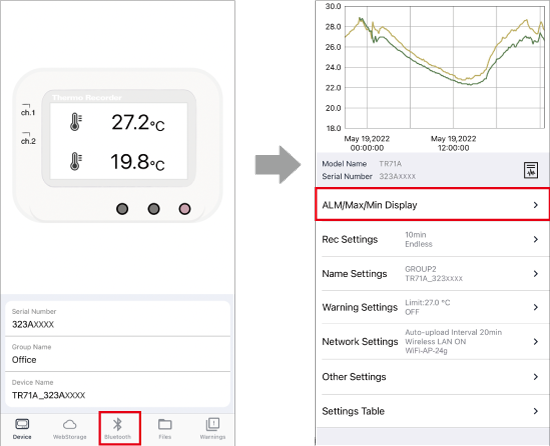
On the Device Info Screen, tap [
 Bluetooth] to open the graph/settings screen.
 -
Tap [ALM/Max/Min Display] - [Clear ALM Display].

*See FAQs - [Device / Power / Sensors] - [Q. What is the difference between Normal and Vaccine Mode?]
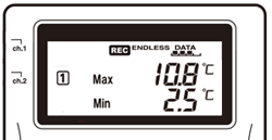
Reset Max/Min Values
The TR7A2/A can display the maximum and minimum measured values for each channel on the LCD.
They can be reset manually or automatically at specific time(s) of the day.
How to Reset Manually
-
On the Device Info Screen, tap [
Bluetooth] to open the graph/settings screen. -
Tap [ALM/Max/Min Display] - [Reset Max/Min Values].
How to Reset Automatically
-
Tap [
Bluetooth] to open the graph/settings screen and tap [Other Settings].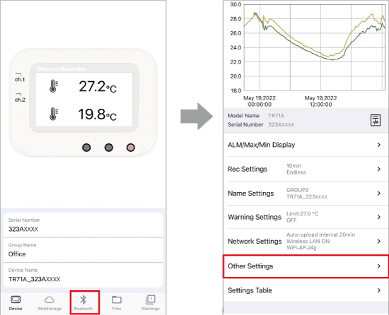
-
If necessary, enable and change the reset times.
(Max/Min Auto Reset Default Settings: Time 1 ON at 0:00 / Time 2 OFF)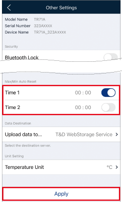
[Other Settings] Screen -
Tap [Apply] to send the settings to the logger.
Configuring Device Settings
On the Device Info screen, tap [Bluetooth] to connect to the device. (Use WLAN Direct Communication for TR-7wf.)
To make settings via cloud, tap [ WebStorage].
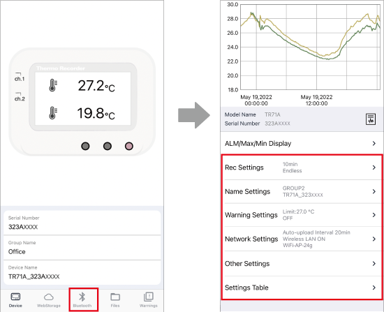
The Device Settings menu is located below the graph.
- When making settings changes via cloud, there are some settings, such as Network Settings, which cannot be changed. The changes will be applied when the logger communicates with the T&D WebStorage Service.
- You can check the device info and settings in [Settings Table].
- The device's default settings can be found in the User's Manual of the data logger.
Recording Settings
The displayed setting items at the monitor will vary depending on the connected device.
Tap [Rec Settings], change the necessary settings, and then tap [Apply] to apply the changes. The logger will start recording based on the settings you made.
Note that all recorded data stored in the logger will be deleted by starting a new recording session.
- Measurement Mode
-
For the Vaccine Mode compatible models (TR71A2/75A2, TR71A/75A), select the Measurement Mode.
- For details of the measurement mode, refer to FAQs - [Device / Power / Sensors] - [Q. What is the difference between Normal and Vaccine Mode?]
- Immediate Start
-
When the setting is applied, the logger starts recording and the [REC] mark will light up on the LCD display.
- Programmed Start
-
Set the date and time to start recording. The logger will enter standby mode and the [REC] mark will blink on the LCD display.
This setting is not available via cloud. - Stop
-
When the setting is applied, the logger stops recording and the [REC] mark on the LCD display will disappear.
- Rec Interval
-
Select from 15 choices: 1, 2, 5, 10, 15, 20, 30 sec. or 1, 2, 5, 10, 15, 20, 30, 60 min.
- 60 min is not available in Vaccine Mode.
- When the device in Vaccine Mode is monitored for warnings, judgments are made at the timing of [Recording Interval]. To quickly detect the out-of-limit condition and sensor error, set a shorter recording interval.
- Rec Mode
-
Endless: Upon reaching the logging capacity, the oldest data will be overwritten and recording will continue.
One Time: Upon reaching the logging capacity, recording will automatically stop.- When Recording Mode has been set to One Time and the logger reaches its logging capacity, recording will automatically stop and in the LCD the measurement and the word FULL will alternately appear.
- Sensor Type (Thermocouple)
-
For the thermocouple sensor compatible models (TR75A2 / 75A, TR-75nw / 75wb / 75wf), select the sensor type.
The LCD screen on the logger displays* the sensor type set here.
Sensor Type: K, J, T, E, S, R- When replacing with a different type of sensor, it is necessary to reconfigure.
- We do not stock thermocouple sensors. Please purchase a compatible sensor.
*On the data logger, press and hold the DISPLAY button. For information on how to read the LCD display, refer to the User's Manual of the data logger.
Logging Capacity:
Please refer to DATA (number of blocks) on the logger's LCD for the amount of data in memory.
![]()
TR7A2/A Logging Capacity: Up to 30000 readings x 2ch
(■: 1 to 9999 readings, ■■: 10000 to 19999 readings, ■■■: 20000 to 29999 readings, ■■■■: 30000 readings)
TR-7nw, TR-7wb/wf Logging Capacity: Up to 8000 readings x 2ch
(■ = 2000 readings)
| Estimated Recording Time | ||
|---|---|---|
| Recording Interval | TR7A2/A | TR-7nw/wb/wf |
| 1 sec | 8 hrs 20 min | 2 hrs 13 min 20 sec |
| 2 sec | 16 hrs 40 min | 4 hrs 26 min 40 sec |
| 5 sec | 1 day 17 hrs 40 min | 11 hrs 06 min 40 sec |
| 10 sec | 3 days 11 hrs 20 min | 22 hrs 13 min 20 sec |
| 15 sec | 5 days 5 hrs | 1 day 9 hrs 20 min |
| 20 sec | 6 days 22 hrs 40 min | 1 day 20 hrs 26 min |
| 30 sec | 10 days 10 hrs | 2 days 18 hrs 40 min |
| 1 min | 20 days 20 hrs | 5 days 13 hrs 20 min |
| 2 min | 41 days 16 hrs | 11 days 2 hrs 40 min |
| 5 min | 104 days 4 hrs | 27 days 18 hrs 40 min |
| 10 min | 208 days 8 hrs | 55 days 13 hrs 20 min |
| 15 min | 312 days 12 hrs | 83 days 8 hrs |
| 20 min | 416 days 16 hrs | 111 days 2 hrs 40 min |
| 30 min | 625 days | 166 days 16 hrs |
| 60 min | 1250 days | 333 days 8 hrs |
| ∗ This does not indicate the period of time allowed for recording without battery replacement. | ||
Name Settings
Tap [Name Settings], change the necessary settings, and then tap [Apply] to apply the changes.
TR7A2/A: Device names can contain up to 26 characters and group/channel names up to 16 characters. (UTF-8)
TR-7wb: Up to 16 characters (UTF-8)
TR-7nw/wf: Up to 16 characters
- Device Name, Group Name, Ch.1 / Ch.2 Names
-
The device name can be edited for easier identification.
These settings are reflected in the T&D WebStorage Service Data View screen, in the Recorded Data file names and within the files themselves, and in the report.- Setting group names will make it possible to view a list of devices by group on the T&D Thermo App and T&D WebStorage Service.
Warning Settings
- In order to receive warning notifications, the device needs to be registered to your T&D WebStorage Service account and configured with automatic data uploading. Email and push notifications will be sent to the email address used at user registration and additional addresses registered under the [Account] menu of T&D WebStorage Service. Warning status and history can also be checked using the T&D Thermo app. (For details, see [Reading the Display] - [Warnings])
- An email notification will be sent to the specified addresses when a warning occurs and recovers. TR7A2/A will also send a notification when the warning is lifted. (Refer to [TR7 Series Warning Transmission Specifications])
- When a warning is detected while the T&D Thermo home screen (list display) is open, you will see [
 Warning] on the device list. It is also possible to set your mobile device's alarm sound and/or vibration whenever a warning notification is received. To make the settings, go to the menu (
 ) (in the upper left corner of the home screen) - [App Settings] - [Warning Notification].
Tap [Warning Settings], change the necessary settings, and then tap [Apply] to apply the changes.
- Sensor Warning / Upper Warning / Lower Warning
-
These parameters can be set for each channel. Sensor Warning will send a notification if a sensor becomes disconnected or fails. Upper Warning and Lower Warning will send a notification if the set limit is exceeded.
Select the judgment time*1 from 9 choices (30 seconds, 1, 2, 5, 10, 15, 20, 30 minutes, and 1 hour).- The limit value is not included in the warning range.
- If the condition recovered within the judgment time, it is not regarded as a warning.
- With the TR7A2/A, the [ALM] icon flashes on the LCD during a warning condition. (See: [Clear ALM Display])
- For TR71A2/71A, TR-71nw/71wb/71wf, the internal sensor*2 of Ch1 allows measurement to continue even if the external sensor is disconnected from Ch1 (not causing a warning). However, in case of sensor fault due to a broken wire, etc., it does not switch to the internal sensor and is regarded as a sensor warning.
*1: For models compatible with Vaccine Mode, the judgment time will be set to 0 second automatically when the Measurement Mode is Vaccine. To quickly detect the out-of-limit condition and sensor error, set a shorter recording interval. (See: FAQs - [Device / Power / Sensors] - [Q. What is the difference between Normal and Vaccine Mode?])
*2: The measured values of the internal temperature sensor will be affected by operating conditions. (See: FAQs - [Device / Power / Sensors] - [Q. Readings from the internal temperature sensor (or the thermocouple) are incorrect, what may be the problem?]) - Battery Warning
-
A low battery may cause communication errors. When the battery warning mark (
 ) appears on the device screen, it is regarded as a warning and notification can be sent.
- For TR-7nw/wb/wf, continuing to use the unit without changing the batteries could lead to loss of recorded data. For TR7A2/A, recorded data will be retained even if battery power is completely gone.
- The battery warning mark will blink or light up depending on the model. (See: FAQs - [Device / Power / Sensors] - [Q. What is the battery life for the data loggers?])
- Update the newest firmware version, when you cannot set up while TR-7nw is connected. For TR-71nw/72nw(-S/-H), the firmware version needs to be 1.11 or higher, and 1.04 or higher for TR-75nw. (See: FAQs - [Device / Power / Sensors] - [Q. How can I check my firmware version and update it when necessary?])
- The TR-7wf does not have the Battery Warning setting. You can check the battery status by the icon in this app or web browser.
Clock Settings and Data Destination
You can make clock settings such as clock synchronization and change the destination of data transmission in [Other Settings].
Change the necessary settings and tap [Apply] to send the settings to the logger.
- Auto-Adjustment
-
You can select how to adjust the internal clock of the device. ([Synchronize with SNTP Server (recommended)] or [Synchronize with T&D WebStorage Service])
- For both options, synchronization occurs when data is first transmitted to the server and when a connection test is performed, then the process will take place every 24 hours.
- [Synchronization with SNTP Server] is recommended due to high accuracy. Enter the SNTP server address if necessary. (EX: time.google.com)
Note
When the device is powered on (for the first time or after a power loss where the LCD display goes off due to a power loss, the internal clock will be reset), manual synchronization* is required once in the following cases:- When [Synchronize with T&D WebStorage Service] is configured for time synchronization.
- When "EAP-TLS" for WPA2 Enterprise in Wireless LAN Settings is configured.
*Connect the device via Bluetooth and perform either of the following operations to synchronize the time manually.
- Select the network in [Network Settings], and conduct the connection test.
- Tap the [Apply] button in [Other Settings] (which will first synchronize the device with your mobile phone before making any other changes).
- Time Zone, Daylight Savings Time
-
Settings for time difference and daylight savings time can be made here.
Default Setting:
UTC+1:00 for Serial Number "No.4XXXXXXX", Daylight Savings Time ON
UTC−8:00 for Serial Number "No.3XXXXXXX", Daylight Savings Time ON
When turning on Daylight Savings Time here, please configure the Clock Display Settings on the T&D WebStorage Service* as well.
* Open your web browser and log in to the T&D WebStorage Service, go to [ Data View] - [Clock Display Settings] and enable the daylight savings time display setting.
 - Data Destination
-
Select the destination server for auto-upload of recorded data.
T&D WebStorage Service: Cloud Service with English display
Ondotori Web Storage (Japan): Cloud Service with Japanese display - Temperature Unit
-
Select Celsius[°C] or Fahrenheit[°F].
Network Settings
- For details about Auto-Upload Settings, see the User's Manual of the data logger.
- Some settings cannot be changed via WebStorage.
- Network Status
-
This shows the network status when the device last connected to the network, or when you performed the connection test for the specified network. (See: [Network Connection Status])
- Wireless LAN
-
Shows the status of wireless LAN connection.
OFF: Select to disconnect the wireless LAN connection and deactivate auto-upload of recorded data and the warning function.
ON: Select to restart the function according to the original settings. - Auto-Upload Interval
-
Select the interval to upload the recorded data: 1, 2, 5, 10, 15, 20, 30 min. 1, 2, 3, 4, 6, 12, 24 hrs.
It is recommended to set auto-upload interval longer than the recording interval.*- When recording mode is set to "One Time" and the logger reaches its logging capacity, recording will automatically stop and data will no longer be updated. In order to upload data continuously, it is recommended to use the "Endless" mode.
- When changing settings via T&D WebStorage Service, the changes will be applied to the device at the time of automatic upload of recorded data.
*In Endless mode, old data will be overwritten if the logging capacity is reached. Overwritten data cannot be sent, therefore make sure to set the device to upload data before reaching the logging capacity to prevent data loss. (See: [Logging Capacity])
- Power Saving Settings
-
Available for the TR7A2 only when the Auto-Upload Interval is three hours or less.
Check the box and select the period of time for pausing Auto-Upload in the range of 6 to 16 hours (in units of 1 hour).- It allows devices to reduce battery consumption. (See: FAQs - [Device / Power / Sensors] - [Q. What is the battery life for the data loggers?])
- If a warning occurs during the paused time period, warning notifications and recorded data up to the time of the warning, will be sent. When the transmission fails, they will be sent at the next auto-uploading cycle.
- Recorded data stored during the paused time period will be sent to T&D WebStorage Service when Auto-Upload* resumes.
- The [Upload] mark will blink on the logger's LCD while Auto-Upload is in pause mode.
* When this transmission fails, a notification can be sent using the Watchdog function of T&D WebStorage Service. (See: [How to Use the T&D WebStorage Service] - [Devices] - [Watchdog Settings] in this help.)
- WLAN Settings (Network 1, 2, 3)
-
Open the setting screen by tapping [+ Add new SSID] to add a new access point or by tapping a network that has already been set, and selecting the menu operation you want.
Edit Network 1, 2, 3: You can change the configuration settings or delete the network. (For details, see [Network Connection Settings])
Add by Search: The app will search for available nearby access points and display them in a list. Select the desired access point and enter the password if necessary.
Add by WPS: If you are using a WPS-enabled wireless LAN access point, it is possible to connect by pressing buttons on both the logger and the access point.
Add from History: Select the desired access point from the archived list of previously used access points. This is especially useful for adding multiple loggers to the same network and can be used for the second and all subsequent loggers.
Test: You can check the network connection status when you change the connection destination or when communication errors occur frequently. (For details, see [Network Connection Status])
Network Connection Settings
Settings can be made for up to three wireless LAN connections (access points). (See: [Using Networks 1, 2, 3])
If necessary, fixed IP addresses and other settings can be entered here.
Supported models by security type are as follows.
WEP: TR-7wb, TR-7wf
WPA/WPA2 Personal: TR7A2, TR7A, TR-7wb, TR-7wf
WPA2 Enterprise: TR7A2
None: TR-7wb, TR-7wf
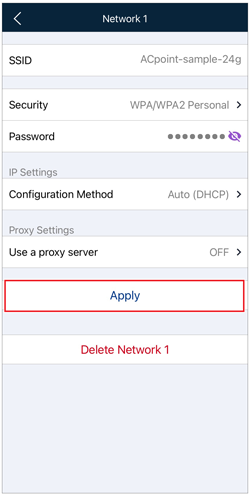
WEP, WPA/WPA2 Personal
Check the entries and tap [Apply].
- Accepted Settings Lengths
-
SSID (Network Name): Up to 32 characters
Security (Password)
WEP: 5 or 13 characters / 10 or 26 digit hexadecimal value
WPA/WPA2 PSK: Password 8 to 63 characters / 64 digit hexadecimal value
Accepted Characters:
0-9 a-z A-Z space ! # $ % & ' ( ) * + , - . / : ; < = > ? @ [ \ ] ^ _ ` { | } ~ - IP Address Settings
-
The factory default setting is Auto (DHCP).
Normally, there is no need to change settings.- When not using DHCP, select "Manual" and then enter necessary information such as the IP address.
- Proxy
-
The factory default setting is OFF.
Normally, there is no need to change settings.- If applicable, check the box [Use a proxy server], then enter the address and port number in the respective fields. A proxy server that requires authentication cannot be used.
- A proxy cannot be used for TR7A2 when using HTTPS. Disable [Secure Connection (HTTPS)] in [Other Settings], and then configure the proxy settings again.
WPA2 Enterprise
The TR7A2 can connect to secure wireless LAN access points that support WPA2 enterprise authentication (IEEE 802.1X authentication).
Compatible Products: TR71A2 / 72A2 / 72A2-S / 75A2
System Requirements
- A wireless LAN access point which supports WPA2 Enterprise
- RADIUS server supporting EAP-PEAP or EAP-TLS
(Access point's RADIUS server function may also be used.)
- Please contact your network administrator directly if you have any questions about preparation or configuration.
- When using EAP-PEAP, server certificate verification by root certificate is not supported.
- IEEE 802.1X authentication is the same for connections 1, 2, and 3. (It is not possible to use different EAP-TLS authentication for each connection point.)
- In order to use EAP-TLS, you need to connect the device to the PC via USB or Bluetooth and configure the Network Settings using Windows Software. For details on necessary information and procedure for setting, refer to TR7 for Windows Help - [Details of Operations] - [About WPA2 Enterprise].
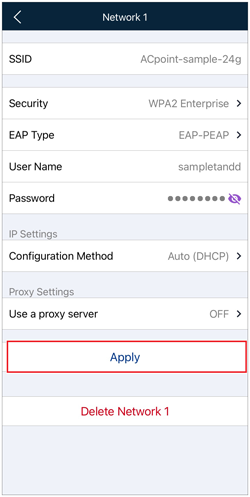
Check the entries and tap [Apply].
- SSID (Network Name)
-
Up to 32 characters
- EAP Type
-
EAP-PEAP:
User ID and Password are required. (Up to 32 characters for each)
Accepted Characters:
0-9 a-z A-Z ! # $ % & ' ( ) * + , - . / : ; < = > ? @ [ \ ] ^ _ ` { | } ~
EAP-TLS:
If it has already been set, tap [Certificate] and open the screen which allows you to check validity period and issuer. - IP Address Settings
-
The factory default setting is Auto (DHCP).
Normally, there is no need to change settings.- When not using DHCP, select "Manual" and then enter necessary information such as the IP address.
- Proxy
-
The factory default setting is OFF.
Normally, there is no need to change settings.- If applicable, check the box [Use a proxy server], then enter the address and port number in the respective fields. A proxy server that requires authentication cannot be used.
- A proxy cannot be used for TR7A2 when using HTTPS. Disable [Secure Connection (HTTPS)] in [Other Settings], and then configure the proxy settings again.
Using Networks 1, 2, 3
Auto-upload Settings can be made for up to three wireless LAN connections (access points). The following describes how the auto-upload function will work in a situation where settings have been made for all three access points.
-
First, the logger will attempt to connect to Network (SSID) 1. If the connection was successful, data will be uploaded without trying to connect to Networks 2 or 3.
-
If the logger was unable to connect to Network 1, it will try connecting to Network (SSID) 2. If successful data will be auto-uploaded without attempting to connect to Network 3.
-
If unable to connect to Network 2, the logger will try to connect to Network (SSID) 3. If the connection is successful data will be automatically uploaded, but if the connection was unsuccessful a communication error will be returned.
Unsent recorded data will be gathered and sent together at the next scheduled auto-upload. However, if while recording in Endless mode, the logging capacity is exceeded by the next transmission, overwritten old data cannot be sent. This means data stored on the T&D WebStorage Service has a missing data.
Network Connection Status
If there is an connection error, check the following depending on the error message.
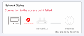
Communication error between device and access point:
- Try adjusting the placement and distance of the logger to the access point.
- Make sure that all wireless LAN access point settings (SSID, Authentication method, Password, etc...) have been made correctly.
Communication error between access point and Internet:
- Check to make sure that an Internet connection can be established on the network you are using.
See if an Internet connection is possible using a PC or some other device that is connected to the same wireless LAN access point, hub, or router. See also, if the Internet connection is restricted by a firewall.
- FAQs - [Functions] - [Q. I cannot view the recorded data that was auto-uploaded to T&D WebStorage Service, what should I do?]
- TR7 for Windows Help - [Detail of Operations] - [Device Operation Log]
Bluetooth Security Settings (A2/A/wb)
You can protect loggers by preventing unauthorized access from other mobile devices via Bluetooth.
Setting the Bluetooth Passcode
- The same passcode can be used for all loggers. (Make the security setting for each unit.)
- If the lock function has been activated and you wish to access the logger from another mobile device (or Windows Software), you need to enter the set passcode.
- The passcode can be found in the Settings Menu - [Settings Table] - [BLE Passcode].
Bluetooth passcode can be reset using the Windows Software by connecting the logger to the PC, but the method differs depending on the model. (See: [Setting Procedure with TR7 for Windows])
-
Open the logger's Setting Menu via Bluetooth and go to [Other Settings].
-
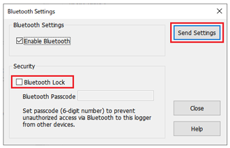
Turn on [Bluetooth Lock] and set a 6-digit passcode.
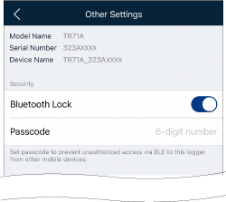
-
Tap [Apply] to send the settings to the logger.
To change the passcode, enter a new passcode and tap [Apply].
Resetting the Bluetooth Passcode (TR7 for Windows)
For details on how to connect devices, refer to TR7 for Windows Help - [Basic Operation Procedures] - [Connecting to a Device].
For TR7A2/A:
-
Open TR7 for Windows and connect the device to the PC via USB or Bluetooth.
-
From the [Settings] menu, open [Bluetooth Settings].
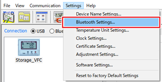
-
Uncheck [Bluetooth Lock] and click the [Send Settings] button.
For TR-7wb:
-
Open TR7 for Windows and connect the device to the PC using a USB cable.
-
Click the [Reset to Factory Default Settings] in the [Settings] menu.
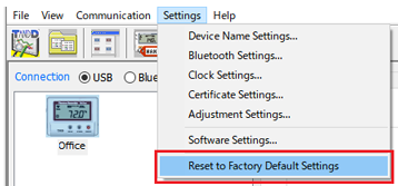
In the case of the TR-7wb, the only way to reset the passcode is to reset the whole device to Factory Default Settings, which means you will have to re-input all the settings for the device which you were using before.
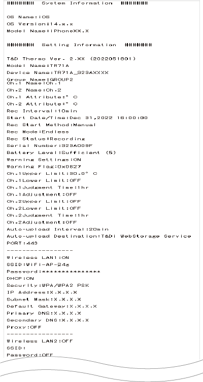
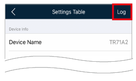
Checking/Exporting Settings Table (A2/A/wb)
Tap and open [Settings Table] to view the settings for the device. By tapping [Log] in the upper right corner of the screen, the settings can be exported to a text file, which can then be sent by email or saved to your mobile device.
Output File Sample