RTR-574/576
Introduction
RTR-574 and RTR-576 are data loggers (Remote Units) equipped with wireless communication technology.
The data recorded by a Remote Unit is collected automatically by a Base Unit via wireless communication and then sent to a computer or cloud storage for archive and analysis.
Here is a description of the device. For the settings, refer to the table below [References for Compatible Base Units and Settings].
| RTR500BW, RTR-500NW/500AW | RTR500BW for Windows section of this Help |
|---|---|
| RTR500BM, RTR-500MBS-A | RTR500BM for Windows section of this Help |
| RTR500BC, RTR-500 | RTR500BC for Windows section of this Help |
| RTR-500DC | RTR-500DC Operation Guide (T&D Website > Support > Manuals & Help Downloads) |
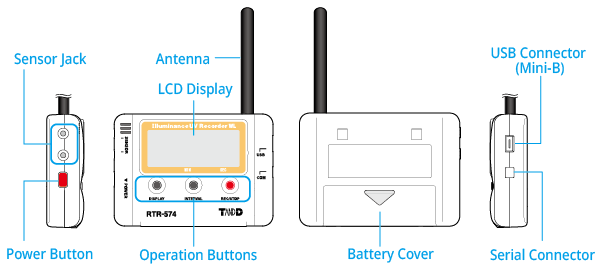
RTR-574: Wireless Illuminance UV Recorder
RTR-574 is a 4-channel data logger for illuminance, UV intensity, temperature and humidity.
RTR-574-S comes with a high precision temp-humidity sensor.
Click on the sensor to read about precautions before using.
| RTR-574 RTR-574-S |
Illuminance/UV Intensity/Temperature/Humidity 1ch each |
Illuminance UV Sensor ISA-3151 Temperature- Humidity Sensor THA-3151 High Precision Temp-Humidity Sensor SHA-3151(S type) |
|---|---|---|
| Included: AA Alkaline Battery LR6, USB Mini-B Cable US-15C, Introductory Manual (including Warranty) | ||
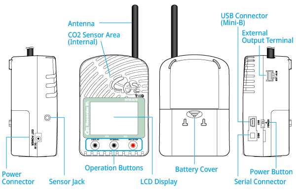
RTR-576: Wireless CO2 Recorder
RTR-576 is a 3-channel data logger for CO2, temperature and humidity, which is suitable for environmental measurements.
RTR-576-S comes with a high precision temp-humidity sensor.
- Measurement results of CO2 concentration are affected by atmospheric pressure. When you need to correct the atmospheric pressure at the measurement location, you can use the Atmospheric Pressure Correction from the Windows software for the Base Unit - Settings Utility - Remote Unit Settings.
- The CO2 calibration function is available to achieve high measurement accuracy. Please read Calibration / Adjustment Function before starting recording.
Click on the sensor to read about precautions before using.
| RTR-576 RTR-576-S |
CO2/Temperature/Humidity 1ch each | CO2 Sensor (Internal) Temperature-Humidity Sensor THA-3001 High Precision Temp-Humidity Sensor SHA-3151 |
|---|---|---|
| Included: AA Alkaline Battery (LR6) x 4, AC Adaptor AD-06A1 or AD-06C1, USB Mini-B Cable US-15C, Manual Set (Warranty Included) | ||
Button Operation
- If "Button Lock" is set to ON in the Windows software, operation buttons will not work except for the DISPLAY button.
- Button operation may not be possible during recording.
- The logger will display the firmware version first after the power is turned on. (For details see: Operational Messages)
REC/STOP: Recording Start/Stop
Press and hold the button until the recording mark (![]() ) appears or disappears.
) appears or disappears.
- It is possible to start recording even if the unit is waiting for a programmed recording to start which can be set via the software.
- Upon the start of recording, all previously recorded data in the unit will be deleted.
DISPLAY: Change Display Mode
RTR-574
- Alternate Display
-
The LCD display shows all or selected multiple measurement items in turn. Make settings for the measurement items to be displayed via the software.
The factory default setting is an alternate display between illuminance and UV intensity. - Fixed Display
-
The LCD display shows one measurement item specified by pressing the DISPLAY button.
With each pressing of the button the measurement Item will change; press until the desired item appears.
RTR-576
- Fixed or Alternate Display
-
Switch between fixed display of either temperature or humidity, or alternating temperature and humidity.
With each pressing of the button the display will change; press until the desired item appears.
The factory default setting is an alternate display.
INTERVAL: Recording Interval
-
Stop recording first.
-
By pressing the button for about two seconds, the currently set recording interval will appear on the LCD display.
With each pressing of the button the recording interval time will change; press until the desired time appears. -
Resume the recording.
Turning Device ON/OFF
Insert the batteries before turning on the power.
RTR-574: Press the red POWER button until the LCD display appears.
RTR-576: Turn the POWER switch up to the ON (triangle mark) position.
Before turning off the power, stop recording.
Even if the power is turned off, the internal data will be retained as long as the battery remains in the unit.
When the RTR-576 is connected to an external power source, the CO2 sensor operates even when the power is turned off, and the light bulb occasionally lights up inside the sensor area.
Calibration of CO2 Sensor (RTR-576)
It is possible to manually calibrate the CO2 sensor by button operation.
Refer to Calibration / Adjustment Function for the method of automatic calibration by software, precautions and operation procedure for manual calibration, etc.
Power
Battery / Power Installation
-
Remove the battery cover and insert the battery, making sure that the plus and minus are in the correct direction.
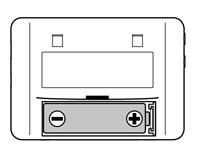
RTR-574 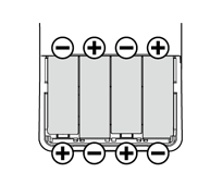
RTR-576 -
For RTR-576: When measuring and recording over long periods of time, please use a supplied AC adaptor.
If running on only batteries, the estimated battery life is about two days. Keeping batteries in the unit allows a backup source of power for when and if electrical power is cut from the AC adaptor.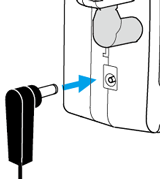
-
Turn ON the Power.
RTR-574: Press the red POWER button until the LCD display appears.
RTR-576: Turn the POWER switch up to the ON (triangle mark) position.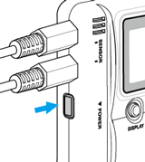
RTR-574 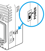
RTR-576 -
The recording mark (
 ) appears and recording starts automatically. When using for the first time, register the logger as a Remote Unit on the Windows software.
Cautions for Changing the Batteries
- For RTR-576: After switching on the unit, it will take about one minute to display the normal CO2 concentration.
- Do not insert or change batteries with wet hands.
- When inserting make sure no water or foreign objects get inside the case.
- When not using the product for long periods, make sure to remove the batteries.
- When resuming use of the product or changing the battery, make sure to use the correct type and size of battery, and ensure that the battery is within the recommended expiration date.
- Please regularly check and replace any batteries installed as backup for an external power supply. Aging batteries may corrode and/or leak.
Battery Replacement (RTR-576)
If the batteries are removed when running on battery power only, the unit will start a sixty-second countdown. To continue recording, before the countdown comes to an end, insert new batteries or connect the AC adaptor to supply power.
If power is not supplied, the unit will enter sleep mode.
Precautions Regarding the Sensors
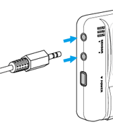
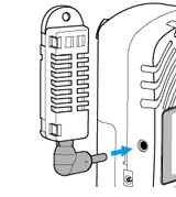
Connect the supplied sensor to the sensor jack.
For RTR-574: The Illuminance-UV Sensor or the Temperature-Humidity sensor can be connected to either jack.
Illuminance-UV Sensor ISA-3151 (for RTR-574)
- Do not connect it to any data logger other than the Illuminance UV Recorder.
- Use the Unit in an environment within the operational range.
- When measuring UV light or other light which may cause damage or injury to your eyes or skin make sure to use protection such as safety glasses or some type of light-proof shield.
- Do not expose the sensor to a strong impact.
- Cracks or scratches in the Illuminance sensor and / or in the UV sensor will adversely affect the measurement accuracy. Also, a broken sensor may result in injury.
- This sensor is not waterproof. By all means do not allow it to get wet.
- Do not expose to condensation, dampness, corrosive gases or organic solvents. Also, do not use in areas near fire or exposed to excessive heat.
- When the Illuminance UV sensor is not being used, please store at room temperature to prevent condensation.
- If the sensor surface gets dirty, wipe it with a soft cloth. If the sensor surface accumulates impurities (dirt), it will cause a decrease in the sensor's accuracy and sensitivity.
- Using the "Adjustment Function" in the software for the Base Unit, it is possible to make desired adjustment settings to a sensor; these settings are saved directly into the sensor itself. Therefore, when a sensor is replaced, it is necessary to re-make any desired adjustment settings to be saved into the newly connected sensor.
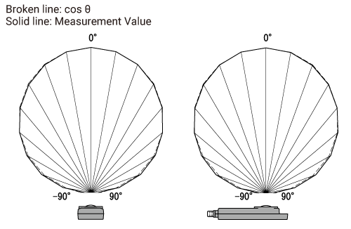
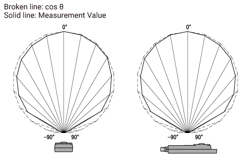
Cosine Correction Characteristics (Illuminance)
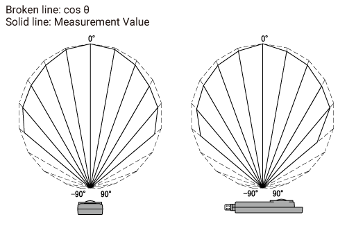
Cosine Correction Characteristics (UV)
Two variations of the sensor are available. They are identified by the serial number (0206XXXX or 0207XXXX) located on the back of the sensor.
Relative Spectral Response Characteristics Graph
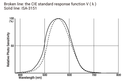

Temp-Humidity Sensors THA-3001 (for RTR-576) / THA-3151 (for RTR-574), High Precision Temp-Humidity Sensor SHA-3151 (for RTR-574)
- If extremely severe temperature changes occur, the humidity measurements may appear abnormal. Once the sensor's temperature becomes stable, the measurements will return to normal.
- Do not connect the sensor to any data logger other than those specified by T&D Corporation.
- Do not expose the sensor to a strong impact. This may adversely affect measurement accuracy and cause damage or malfunction.
- When the sensor is not to be used for a long period of time, please store it at normal temperature and humidity.
- Do not use the sensor on the human body.
- Do not expose to condensation, dampness, corrosive gases, or organic solvents.
- Continued use may cause a decrease in the sensor's accuracy and sensitivity even under normal operational conditions.
- This sensor is not water resistant. Do not allow the sensor to become wet. If the sensor gets wet, immediately remove the sensor from the unit and wipe it with a clean cloth as soon as possible. Then allow the sensor to dry in normal room temperature before using it again.
- When using the THA-3001 or THA-3151 in an environment where the humidity is under 30 %RH, the measurements may sometimes fluctuate. This is not abnormal.
- When the SHA-3151 is continually used in environments with temperatures above 60°C, accuracy of humidity measurements will decrease over time. Also, humidity cannot be measured at temperatures below −20°C.
CO2 Sensor (built in RTR-576)
- This product has been designed for use in normal living conditions, and is not suited for controlled environments such as a CO2 incubator. When measuring outdoors, avoid exposure to sunlight, dust, rain, or wind. Also make sure to use in the operating environment indicated in the specifications.
- This product cannot measure CO or O2. Do not use it for purposes such as avoiding O2 deficiency, CO intoxication or any other health related purpose.
- For one to two weeks after installation of the unit, CO2 concentration measurements may fluctuate suddenly. This is due to the normal operation of Auto Calibration and is not a malfunction of the unit.
- Do not use or store the unit in areas exposed to direct sunlight and abrupt changes in temperature.
- Do not allow the unit to become wet. Do not use or store the unit in places where condensation occurs.
- To help prevent deterioration of the unit, do not use or store the unit in areas exposed to cigarette smoke, corrosive, explosive or organic gases or dust in the air.
- Do not expose the unit to a strong impact. This will adversely affect measurement accuracy and may cause the case to break resulting in bodily injury.
- The measurement accuracy of the CO2 sensor cannot be guaranteed for CO2 concentrations of 5,000 ppm or more.
Basic LCD Display


Recording Status
ON: Recording in progress.
BLINKING: Waiting for programmed start.
OFF: Recording has been stopped.

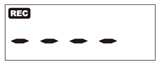
Data Scale
At the beginning of every 2,000 readings the scale will be marked from left to right. Logging capacity is 8,000 readings.

Communication Status
Shows communication status but not displayed normally.
ON: The Unit is connected to a PC with the USB cable.
BLINKING: The unit is in wireless, USB or serial communication.

Recording Mode
ENDLESS: Upon reaching logging capacity of 8,000 readings, the oldest data is overwritten and recording continues.
ONETIME: Upon reaching logging capacity of 8,000 readings, recording will automatically stop.
The factory default setting is Endless.

Battery Level
RTR-574
When it is time for the battery to be replaced, ![]() will appear.
will appear.
RTR-576
The battery level will be shown in three stages as below. The icon will flash when running on batteries.
 OK
OK
 Getting Low
![]() Too Low
Too Low
- If the battery power has become low while running on batteries only, it is impossible to measure and record CO2 concentration. Also, errors may occur during wireless communication.
- When running on batteries only, the estimated time until
 (Too Low) appears is about 2 days.
 - Also refer to Operational Messages for sleep mode due to low battery.
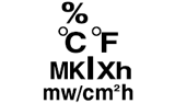
Units of Measurement (RTR-574)
Includes units of measurement for humidity, temperature, illuminance and UV intensity.
For Illuminance and UV Intensity data, cumulative measurements can also be viewed.
Cumulative Illuminance: lxh、klxh、Mlxh
Cumulative Amount of UV Light: mW/cm²h、W/cm²h

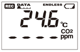
Units of Temp / Humidity (RTR-576)
The upper part of the screen displays the current readings of temperature and/or humidity.

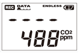
Units of CO2 Concentration (RTR-576)
The lower part of the screen displays the current readings of CO2 concentration.
Operational Messages
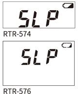
SLP (Sleep Mode)
After the (![]() /
/![]() ) stage, if the batteries are not changed but remain in use, the unit will enter sleep mode and stop measurement and recording in order to protect recorded data until this point.
) stage, if the batteries are not changed but remain in use, the unit will enter sleep mode and stop measurement and recording in order to protect recorded data until this point.
- Attempting to download recorded data in this state may cause the loss of data during communication.
- Recording cannot continue even if the battery is replaced at this point. Stop recording and download the recorded data before resuming the recording.
- If the battery is further left unchanged, the display will automatically shut off and all previously recorded data will be lost.
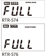
FULL (Logging Capacity FULL)
When Recording Mode has been set to ONETIME and the Unit reaches its logging capacity of 8,000 readings, recording will automatically stop and in the LCD the current measurement and the word "FULL" will alternately appear.
Stop recording and download the recorded data before resuming the recording.
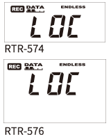
LOC (Button Lock)
By setting the "Button Lock" to ON in the Settings Utility or the mobile app, the operational buttons on the unit will be inactive.
Sensor Unconnected (RTR-574)
If after re-connecting the sensor and measurements can still not be displayed, it is very possible that the sensor or the Unit are defective or have been damaged.
Measurement and recording will continue so battery power will be consumed.
Temp-Humidity Sensor Unconnected (RTR-576)
If after re-connecting the sensor and measurements can still not be displayed, it is very possible that the sensor or the Unit are defective or have been damaged.
Measurement and recording will continue so battery power will be consumed.
CO2 Sensor Error (RTR-576)
This appears when power has just been turned ON. If measurements don't appear in the display after waiting for a considerable time, there is a possibility that the sensor is defective or has been damaged. Also, the CO2 sensor will not work if battery power is low.

Firmware Version
When the power is turned ON, the logger will display the firmware version for about 2 seconds. You can also check the firmware version on the Windows software.
External Alarm Terminal (RTR-576)

| Enabling Warnings | ① | Warning Output (Enable / Disable) | Internal Pull-up: 3V 100KΩ Maximum Input Voltage: 30V |
|---|---|---|---|
| ② | GND | ||
| Warning Output (OUT) | ③ | Output Terminal (Warning Output) | Open Drain Output Voltage when OFF: DC less than 30V Current when ON: less than 0.1A Resistance when ON: 15Ω |
| ④ | GND |
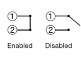
The connection between ① and ② decides whether Warning Output is enabled or disabled.
If a warning condition occurs while Warning Output is enabled, a connection between ③ and ④ will be established and a warning will be output.
The optional alarm connection cable (AC0101) is available. Please contact your local distributor for purchase.
Calibration / Adjustment Function
Auto Calibration of CO2 Sensor (RTR-576)
Auto calibration is a function designed to enable long-term accurate measurements for the RTR-576 by gradually adjusting the lowest measured CO2 concentration over a 180 hour period, to the global average concentration (atmospheric CO2 level of around 400 ppm).
Although the factory default setting for auto calibration is ON, it is not suitable for continuous measurement in an environment where the CO2 concentration is always high or low (the lowest weekly CO2 concentration differs greatly from 400 ppm).
Specifically, turn it OFF in the following environments.
- Areas with higher CO2 concentration (compared to the atmospheric level of 400 ppm), such as a workplace that operates on 24-hour schedules where people are constantly working.
- Areas with lower CO2 concentration (compared as to the atmospheric level of 400 ppm), such as greenhouses and plant factories where plants absorb CO2 as they grow.
- When auto calibration is set to OFF, the measurement of the CO2 sensor may have a slow drift. To ensure accurate measurement results, periodically place the RTR-576 in fresh air outside and check if the measured CO2 concentration values are close to 400 ppm or not. If not, we recommend that you carry out manual calibration.
- By changing the auto calibration settings, all recorded data stored in the RTR-576 will be erased. We suggest that you download the recorded data in advance.
Auto Calibration ON/OFF
The auto calibration setting can be changed using the software for your Base Unit.
-
Open the Settings Utility from the Windows software for the Base Unit (e.g. RTR500BM for Windows), and open the settings window for the Base Unit connected via USB or LAN.
-
Open the [Remote Unit Settings] menu.
-
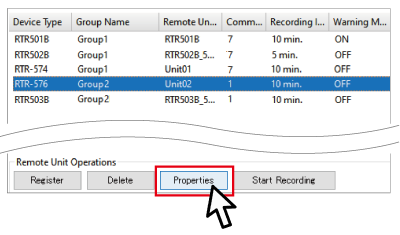
Select the RTR-576 for which you want to change the settings from the list, and click [Properties]. (If it has not been registered yet, click [Register].)
-
Connect the RTR-576 via USB to the computer.
Settings table will appear. -
Change the Auto Calibration ON or OFF. (Please refer here for other setting items.)
-
Click the [Apply] or [Register] button.
-
You will be prompted to power cycle the RTR-576.
(Unplug the AC adaptor and turn off the POWER switch, and plug the AC adaptor and turn on POWER again.)
- If you cannot select Auto Calibration ON/OFF, the version of the software (e.g. RTR500BM for Windows) may be old. Update the software to the latest version, and then open the [Remote Unit Settings] menu again.
- If you do not power cycle the RTR-576 as prompted, the changes to the settings will not actually take effect even though the display indicates that the settings are complete. Make sure to follow the instructions as they appear on the PC screen.
Manual Calibration of CO2 Sensor (RTR-576)
Here are the procedures for calibrating the CO2 sensor manually using the buttons on the RTR-576.
You can reset the CO2 measurement offset to match the atmospheric normal concentration of around 400 ppm.
- Operate calibration outdoors.
- Before the operation, stop recording.
- Make sure there is ample battery power.
-
Turn OFF the POWER switch on the unit.
-
While holding down the DISPLAY button, turn on the POWER switch.
Keep holding down the DISPLAY button until you see [CAL] in the display. -
Let go of the DISPLAY button.
-
Push the DISPLAY button again, and the upper row of the display will show [CAL] while the lower row will show the CO2 concentration.
Push the INTERVAL button to switch between [=Air] and [=0]. Let go of the button when [=Air] is displayed.
-
Step away from the unit, and wait until the CO2 concentration becomes stable.
-
Once the measurement becomes stable, push the REC/STOP button.
[CAL] turns to [SET] when the calibration process begins. -
In about a minute, calibration will be completed and the display will return to normal.
Check to make sure that the measured CO2 concentration values are close to 400 ppm.
Adjustment of Measurements
By using Adjustment Tools, it is possible to adjust the readings measured by Remote Units.
Adjustment for differences will be carried out using an adjustment equation of y=ax+b; where x is the pre-adjusted reading (Current Reading) and y is the post-adjusted reading.
- 1 Point Adjustment
-
Use this to adjust all measurements with the same offset. (The whole graph will be adjusted up or down, keeping the same slope.)
- 2 Point Adjustment
-
Use this to adjust measurements in a wide range or when adjustment cannot be carried out using only one point. (The slope will change.)
T&D Website > Software/Apps > Adjustment Tools
- We cannot guarantee that after carrying out adjustment of the measurement, accuracy will improve for all measuring ranges.
- When making adjustments to Illuminance and UV Intensity, it is recommended to use a point closest to "zero" for adjustment.
- Adjustment function is set in the sensor, and the settings will remain even if the Remote Unit is initialized. To initialize the adjustment settings, use the Adjustment Tools.
- When a sensor is replaced, it is necessary to re-make any desired adjustment settings before using the new sensor.
- If you want to make adjustments to a sensor that has already been adjusted, initialize the setting first.
Device Initialization
To initialize the data logger, use the Windows software for your Base Unit.
For details about operation, see the following sections of this Help.
- [RTR500BW for Windows]-[Settings Utility Main Window]-[Operation] Menu
- [RTR500BC for Windows]-[Base Unit Settings]-[Tools]
Before initializing the device, unplug the sensor.
Updating the Firmware
The firmware update requires a USB connection between the logger and a PC.
-
Open the Windows software and click [Update Information]* in the launcher window.
-
Click [Get Update Information] to view the updates for the software and firmware available for compatible devices.
-
Select RTR-574 Firmware Update Tool or RTR-576 Firmware Update Tool.
-
Click [Download Selected Update] to open the download page in your browser.
-
Download and install the update tool on your PC to update the firmware of the unit connected via USB.
* Notifies the latest information on the software and firmware on the Internet.
For how to check the firmware version of your device, please refer to Operational Messages.
- Details such as the update procedure and update details are also explained on the Software/Apps download page of our website; please check when downloading the update tool.