RTR501B/502B/503B/505B/507B
Introduction
RTR501B, RTR502B, RTR503B, RTR505B and RTR507B are wireless data loggers (Remote Units) of RTR500B Series that supports special low power wireless communication and Bluetooth® Low Energy.
The data recorded by a Remote Unit is collected automatically by a Base Unit via wireless communication and then sent to a computer or cloud storage for archive and analysis.
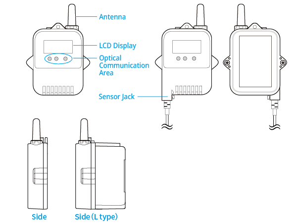
- Here is a description of the device. For the settings, refer to the table below [References for Compatible Base Units and Settings].
- When using the RTR500BW or RTR500BM as a Base Unit, it is possible to carry out device registration and settings using the mobile app T&D 500B Utility in addition to the Windows software.
- When using the RTR500BC or the discontinued RTR-500 series model (RTR-500NW, RTR-500AW, RTR-500MBS-A, RTR-500, RTR-500DC) as a Base Unit, the Bluetooth function of the Remote Unit will be disabled upon device registration using the Windows software. It will be enabled by initializing the Remote Unit.
| RTR500BW RTR-500NW/500AW* |
T&D 500B Utility Mobile App or RTR500BW for Windows section of this Help |
|---|---|
| RTR500BM RTR-500MBS-A* |
T&D 500B Utility Mobile App or RTR500BM for Windows section of this Help |
| RTR500BC RTR-500* |
RTR500BC for Windows section of this Help |
| RTR-500DC* | RTR-500DC Operation Guide (T&D Website > Support > Manuals & Help Downloads) |
| *RTR-500 series models do not have Bluetooth capability. T&D 500B Utility Mobile App does not support the RTR-500NW/500AW and RTR-500MBS-A. | |
Click on the sensor or module to read about precautions before using.
| Model | Measurement Channels | Sensor (Included) | Input Modules (Option) |
|---|---|---|---|
| RTR501B/ 501BL |
Temperature 1ch | − | − |
| RTR502B/ 502BL |
Temperature 1ch | Temp Sensor TR-5106 | − |
| RTR503B/ 503BL |
Temperature 1ch, Humidity 1ch | Temp-Humidity Sensor TR-3310 | − |
| RTR505B/ 505BL |
Temperature(TC) Temperature(Pt1000/Pt100) Voltage(V) 4-20mA Pulse(P) 1ch (Measurement item depends on the input module and sensor) |
Sensor not included | Thermocouple Module TCM-3010 PT Module PTM-3010 Voltage Module VIM-3010 4-20mA Module AIM-3010 Pulse Input Cable PIC-3150 |
| RTR507B/ 507BL |
Temperature 1ch, Humidity 1ch | High Precision Temp-Humidity Sensor SHB-3101 | − |
| Common Accessories: Lithium Battery LS14250 (or Large Capacity Battery Adaptor Kit RTR-500B1 for L type model), Strap (Not included with L type model), Manual Set (Warranty Included) (L-type models (model names which include "L") are designed with a large capacity battery kit. Battery life of the L type is four times longer than that of the normal type.) |
|||
Battery Installation and Replacement
When the battery is inserted, recording will start automatically with the default or previous settings.| Default Settings | |
|---|---|
| Recording Mode | Endless |
| Recording Interval | 10 minutes |
| Recording Start Method | Immediate Start |
| Sensor Mode (RTR505B) | Undefined |
You can check if the battery needs replacement by looking at the LCD screen of the Remote Unit, have a warning email sent, or by viewing the T&D WebStorage Service Data View page, Windows Software or Mobile App screen.
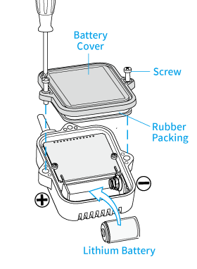
When you install or replace the battery, follow the precautions below to keep the waterproof performance of the Remote Unit.
Notes about Remote Units with Lithium Batteries
- If a new battery has been installed and recording does not immediately start, nothing appears in the display or any other such malfunction, please remove the battery, check to make sure plus and minus are correct and re-insert the battery.
- When using for the first time, it may take a few seconds after inserting the battery to start recording; this is not a malfunction.
- After the battery installation, the battery warning mark may not disappear from the logger's LCD for 10 to 60 minutes. This is due to the characteristic of the lithium battery and is not a malfunction of the logger or the battery.
- Please store the LS14250 in a place that is 20 °C or less.
- When using lithium batteries other than LS14250 produced by SAFT, such as CR2, product specifications cannot be guaranteed nor can the performance of some functions, such as the battery warning function.
Please avoid using the CR2 in the following situations:
Using the unit in an environment below 0 °C or above 60 °C
Exposing the CR2 to continuous vibration such as in transportation - When using a CR2 lithium battery, the tube is not necessary.
- To maintain waterproof capacity, when changing batteries also change the rubber packing and the drying agent (silica gel). When using a CR2 lithium battery, please purchase the optional Maintenance Set TR-00P1 to replace the rubber packing and silica gel.
Operating Environment
- In low temperature conditions communication may become unstable, even if sufficient battery power remains.
- Avoid long-term use in environments of 60 °C or higher, as the unit itself and the parts inside will deteriorate more rapidly.
- Compared to the battery life under normal temperature conditions (about 10 months*), the battery life under the following conditions will be shorter as shown below.
−20 °C: one half of life compared to normal temperatures
−30 °C: one third of life compared to normal temperatures
60 °C: one half of life compared to normal temperatures
*Assuming a recording interval of 10 seconds or more, current readings transmission every 10 minutes, and recorded data transmission once a day.
Precautions Regarding the Sensors and Input Modules
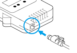
Make sure that the sensor or module is completely inserted until you hear a "click" sound.
Temperature Sensor TR-5106 (for RTR502B)
- Do not bend or press the last 5cm to the tip of the sensor, as this may damage it.
- Do not cut or process the cable.
- If the FEP coating on the sensor and/or the cable has a defect or tear, the waterproof capacity will be lost. Inspect it before operation.
- Insert the sensor tip to at least 5cm or more to obtain an accurate temperature measurement.
- Use the sensor within its resistance range.
- It can be extended by 3 meters with the Extension Cable TR-2C30 (sold separately).
Temp-Humidity Sensor TR-3310 (for RTR503B) / High Precision Temp-Humidity Sensor SHB-3101 (for RTR507B)
- This sensor is not water resistant.
- Do not expose to condensation, dampness, corrosive gases or organic solvents. If the sensor gets wet, immediately remove the sensor from the unit and wipe it with a clean cloth as soon as possible. Then allow the sensor to dry in normal room temperature before using it again.
- Do not expose the sensor to a strong impact. This may adversely affect measurement accuracy and cause damage or malfunction.
- Continued use may cause a decrease in the sensor's accuracy and sensitivity even under normal operational conditions. Periodic calibration may be required.
- When the sensor is not to be used for a long period of time, please store it at normal temperature and humidity.
- When the SHB-3101 is continually used in environments with temperatures above 60 °C, accuracy of humidity measurements will decrease over time. Also, humidity cannot be measured at temperatures below −20 °C.
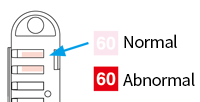
- The TR-3310 has a temperature detection sticker attached to the sensor. If the color changes from light pink (normal) to red, replace with a new sensor.
Thermocouple Module TCM-3010 (for RTR505B)
Insert the miniature thermocouple connector, aligning as shown on the input module. When inserting a sensor into an input module, make sure to match the plus and minus signs on the sensor connector to those on the module.
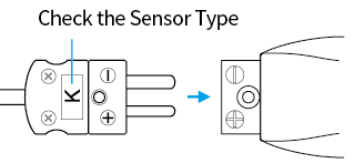
- The data logger detects disconnection about every 40 seconds, causing it to display an incorrect temperature directly after a connector is removed.
- Make sure that the thermocouple type (K, J, T, or S) of the sensor to be connected to the input module, and the sensor type to be displayed on the LCD screen of the data logger are the same. If they are different, change the sensor type using the software or app.
- Measurement range is in no way a guarantee of the sensor heat-durability range. Please check the heat-durability range of the sensor being used.
- "Err" will appear in the display of the data logger when a sensor has not been connected, has been disconnected or a wire has been broken.
- When you wish to use a different type of input module or cable, it is first necessary to initialize the Remote Unit and redo the Remote Unit registration and sensor settings before connecting the new one.
PT Module PTM-3010 (for RTR505B)
- Loosen the screws of the terminal block.
- Slide the sensor cable terminals through the input module protective cover.
-
Insert terminals A and B according to the diagram shown on the terminal block and re-tighten the screws.
In the case of a 4-wire sensor, one of the A wires will be left disconnected.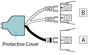

Protective Cover
- Make sure that the sensor type (100 Ω/1000 Ω) to be connected to the input module, and the sensor type to be displayed on the LCD screen of the data logger are the same. If they are different, change the sensor type using the software or app.
- Make sure to correctly connect the lead wires according to the diagram shown on the terminal block, and securely tighten the screws to the terminal block.
- The two "B" terminals have no polarity.
- Measurement range is in no way a guarantee of the sensor heat-durability range. Please check the heat-durability range of the sensor being used.
- "Err" will appear in the display of the data logger when a sensor has not been connected, has been disconnected or a wire has been broken.
- When you wish to use a different type of input module or cable, it is first necessary to initialize the Remote Unit and redo the Remote Unit registration and sensor settings before connecting the new one.
4-20mA Module AIM-3010 (for RTR505B)
Use a tool such as a screwdriver to press down on the terminal button and insert the wire through the hole.
When removing, do not forcibly pull on the wire, but push down on the button as done when installing and gently pull the wire out of the hole.

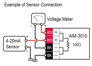
It is possible to connect a different high impedance device such as a voltage meter to the empty terminals of the module.
- Do not apply electric current exceeding the input current range. Doing so may damage the input module, causing heat or fire to occur.
- When you wish to use a different type of input module or cable, it is first necessary to initialize the Remote Unit and redo the Remote Unit registration and sensor settings before connecting the new one.
Voltage Module VIM-3010 (for RTR505B)
Use a tool such as a screwdriver to press down on the terminal button and insert the wire through the hole.
When removing, do not forcibly pull on the wire, but push down on the button as done when installing and gently pull the wire out of the hole.

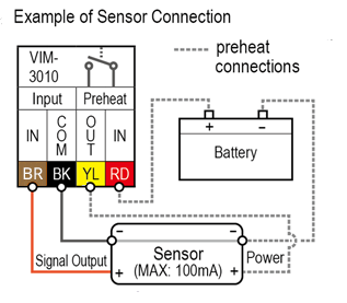
- It is not possible to measure negative voltage with this module.
- When you remove the lead wires from the VIM-3010, core wires will be exposed; be careful of electrical shocks and/or short circuits.
- When the signal source output impedance is high, a gain error will occur due to the change in input impedance.
Voltage to be input to "Preheat" should be 20V or lower. Inputting a higher voltage may cause damage to the input module. - When the preheat function is not being used, do not connect anything to the "Preheat IN" or "Preheat OUT".
When using the preheat function, it is necessary that the output signal GND (−) and the power GND (−) are connected together. - The LCD refresh interval for the data logger is basically from 1 to 10 seconds, but when using the preheat function the LCD display will be refreshed based on the recording interval set in the data logger.
- When you wish to use a different type of input module or cable, it is first necessary to initialize the Remote Unit and redo the Remote Unit registration and sensor settings before connecting the new one.
Pulse Input Cable PIC-3150 (for RTR505B)
When connecting the cable to the measurement object, in order to wire properly
make sure to match the terminal polarities (RD+, BK−).
- When you wish to use a different type of input cable or module, it is first necessary to initialize the Remote Unit and redo the Remote Unit registration and sensor settings before connecting the new one.
Basic LCD Display
The LCD may become difficult to read when used in very hot or cold environments.

Recording Status
ON: Recording in progress
BLINKING: Waiting for programmed start
OFF: Recording stopped

Recording Mode
ON: One Time (Upon reaching the logging capacity, recording will automatically stop.)
OFF: Endless (Upon reaching the logging capacity, the oldest data will be overwritten and recording will continue.)
- The factory default setting is "Endless".

Battery Warning Mark
Appears when the battery is low.
Also refer to Operational Messages for low battery.

Measurement Unit
Shows the unit of measurement.

Pt / Thermocouple Sensor Type
![]() : Pt100
: Pt100
![]() : Pt1000
: Pt1000
![]() : Thermocouple Sensor Type
: Thermocouple Sensor Type
- Shows the type of sensor set (It does not automatically detect the connected sensor.)
- When you replace the sensor with another type, you need to make the sensor settings on Windows software or mobile app.

Ir Mark
Indicates that the logger (Remote Unit) has not been registered to the Base Unit or the wireless communication is stopped (inactive radio).

Bluetooth Communication Status
Indicates that the device is in Bluetooth communication.
RTR505B Display Examples
Display varies depending upon the input module connected.

Thermocouple Module TCM-3010
Unit: °C / °F
The thermocouple sensor type selected in the Remote Unit Settings will appear below the measurement: K, J, T, or S.
- The factory default setting is type K.
- When you replace with a different type of sensor, make sure to change this setting before starting the measurement.

PT Module PTM-3010
Unit: °C / °F
The thermocouple sensor type selected in the Remote Unit Settings will appear below the measurement: Pt (Pt100) or PtK (Pt1000).
- The factory default setting is Pt (Pt100).
- When you replace with a different type of sensor, make sure to change this setting before starting the measurement.
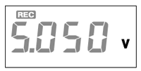
Voltage Module VIM-3010
Unit: V, mV
Due to the wide measurement range, the device has been set by default to adjust the decimal point automatically to display the measurement in V.
The unit of display can be changed in the Remote Unit Settings of the software or app.
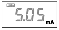
4-20mA Module AIM-3010
Unit: mA
4-20mA measurement will be displayed.
When the Pulse Input Cable PIC-3150 is connected, there are two display methods for the pulse measurement. The display method can be changed in the Remote Unit Settings of the Settings Utility software for the Base Unit.
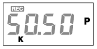
Pulse Rate (Max: 61439)
Unit: P, KP
The most recent pulse count for the recording interval period will be displayed.
The display will be refreshed every one-sixtieth of the recording interval (at minimum of every one second).
50,500 pulse count will be displayed as [50.50P] with "K" below the measurement value. The display is in units of 10 pulses.
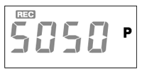
Total Pulse Count
Unit: P
The cumulative number of pulses (Unit: P) will be displayed from 0 to 9999.
The displayed count will be refreshed every one second, and upon exceeding 9999, the count will start over again from 0.
Operational Messages
Battery Related
The following battery related messages may be displayed after the battery warning mark (![]() ).
).

Insufficient Battery Power
If you continue to use the logger without changing the battery, the current temperature and [bAtt] will be displayed alternately.
- Attempting to download recorded data in this state may cause the loss of data during communication.
- Communication errors may occur frequently.
- If you take no action until the LCD display goes blank, all recorded data in the Remote Unit will be lost. The settings will remain.

CHEC
This will be displayed under the following conditions:
- When installing the battery after purchase or initialization of the device.
- If the battery is left unchanged or replaced after having been taken out for a long period (All data in the logger will be lost.)
Transmission and Capacity

Data Transmission via Wireless Communication
The measurement and the word [SEnd] will alternately appear when data is being sent via wireless communication to the Base Unit. Recording will continue during wireless transmission.

Logging Capacity FULL
When recording mode is set to "One Time" and the logger reaches its logging capacity, recording will automatically stop and in the LCD the measurement and the word [FULL] will alternately appear.
Estimation of time until [FULL] is displayed
| Recording Interval | 1 second | 30 seconds | 10 minutes | 60 minutes |
|---|---|---|---|---|
| RTR501B/502B/505B | About 4 hours and 26 minutes | About 5 days and 13 hours | About 111 days | About 1 year and 10 months |
| RTR503B/507B | About 2 hours and 13 minutes | About 2 days and 18 hours | About 55 days | About 11 months |
Sensor / Module Connection

Sensor Error
This will appear when a sensor has not been connected or the wire has been broken.
If after re-connecting the sensor, measurements can still not be displayed, it is possible that the sensor or module is defective or has been damaged.
- For RTR507B, this also appears when the battery is too low to continue measurement.

Input Module Error
This will appear when the input module is not connected to RTR505B.
For RTR502B

Measurement Range Exceeded
The current temperature display will blink when the temperature goes below −60 °C or above +155 °C.
For RTR505B

Sensor Unconnected or Damaged
This will be displayed when a thermocouple or Pt sensor has not been connected to the input module or the wire has been broken. Recording is in progress and so is battery consumption.

Measurement Range Exceeded
[OL] will appear if a measurement exceeds the measurement range.

Display Range Exceeded
When measuring voltage in mV range, the measurement in the LCD display will flash if it exceeds the display range of the device.
Measurement Adjustment Function
Using the software Adjustment Tools, it is possible to make adjustments to Remote Unit measurements.
Adjustment for differences will be carried out using an adjustment equation of y=ax+b; where x is the pre-adjusted reading (Current Reading) and y is the post-adjusted reading.
- 1 Point Adjustment
-
Use this to adjust all measurements with the same offset.
- 2 Point Adjustment
-
Use this to adjust measurements in a wide range or when adjustment cannot be carried out using only one point.
T&D Website > Software/Apps > Adjustment Tools
- We cannot guarantee that after carrying out adjustment of the measurement, accuracy will improve for all measuring ranges.
- When making adjustments to Voltage or 4-20mA, it is recommended to use a point closest to "zero" for adjustment.
- Adjustment settings are made on the sensor/module connected to the Remote Unit, and the settings will remain even if the Remote Unit is initialized. To reset the adjustment settings, use the Adjustment Tools software and perform the initialization.
- When a sensor or module is replaced with a new one, it is necessary to re-make any desired adjustment settings.
- If you want to make adjustments to a sensor or module that has already been adjusted, initialize the settings first.
Device Initialization
Please initialize the Remote Unit in the following cases.
- When the Remote Unit is deleted from the Base Unit's registration list.
- When changing the type of input module or cable to connect to RTR505B or RTR-505.
For details about operation, see the following sections of this Help.
- [T&D 500B Utility Mobile App] - [Tools]
- [RTR500BW for Windows] - [Settings Utility Main Window]
- [RTR500BC for Windows] - [Software Operational Settings] - [Tools]
Before initializing the device, unplug the sensor and input module/cable from the device.
Firmware Update
Firmware update can be performed by using the mobile app T&D 500B Utility (for iOS).
(The discontinued RTR-500 series models are not supported.)
Search for T&D 500B Utility in the App Store to install or update.
- Individual update function (for each device) is supported by App Ver.1.21 or later, and Bulk update function (for multiple devices) is supported by App Ver.1.22 or later.
- For the update procedures and precautions, please refer to the [T&D 500B Utility Mobile App] - [Tools] - [Updating Remote Unit Firmware] in this help.

