RTR500BW/500BM/500BC
RTR500BW
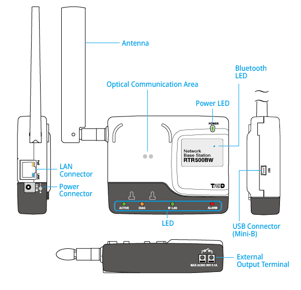
RTR500BW is a Base Unit equipped with wired and wireless LAN functionality. Measurement data gathered via wireless communication from target Remote Units can be automatically uploaded to our cloud storage service T&D WebStorage Service. Remote monitoring, warning monitoring and device settings can also be carried out via the cloud service.
Also equipped with Bluetooth® and USB functions, it can be set on either a smartphone or a PC.
Here is a description of the device. For details about settings see [T&D 500B Utility Mobile App] or [RTR500BW for Windows].
| Compatible Devices | |
|---|---|
| Remote Units | RTR500B Series Data Loggers: RTR501B/502B/503B/505B/507B (Including L Type) RTR-500 Series Data Loggers:* RTR-574/576 (Including S Type), Discontinued: RTR-501/502/503/507S/505-Pt/505-TC/505-mA/505-V/505-P (Including L Type) RTR-600 Series Data Loggers:* RTR-602S/602L/602ES/602EL Discontinued: RTR-601-110/130/E10/E30 |
| Repeaters | RTR500BC (Discontinued*: RTR-500) |
| * RTR-500 Series loggers and Repeaters, as well as, RTR-600 Series loggers do not have Bluetooth capability. | |
Included: USB Cable US-15C, AC Adaptor AD-05A4 or AD-05C1, Registration Code Label, Manual Set (Warranty Included)
About the LED Display
| LED(color) / Status | Device Status | |
|---|---|---|
| Power (green) |
ON | Power is "ON" |
| Bluetooth Communication (blue) | ON | Bluetooth Communication is set to ON |
| BLINKING | Bluetooth Communication in progress... | |
| ACTIVE (green) |
ON | Network communication available / Connected via USB |
| BLINKING | Network or USB Communication in progress... | |
| DIAG (orange) |
ON |
|
| W-LAN (green) |
ON | Wireless LAN Communication Possible (Wired LAN Communication not available*) |
| BLINKING | Wireless LAN Communication in progress... | |
| ALARM (red) |
BLINKING | Warning Issued (One of the following warnings was issued: Upper or Lower Limit Exceeded, Wireless Communication Error, Sensor Error, Low Battery) |
| Ethernet Port POE (orange) | ON | Power being supplied |
| Ethernet Port LINK (green) | BLINKING | LAN Communication in progress... |
| * Use by selecting either wired or wireless LAN. If wireless LAN is active, wired LAN cannot be used. | ||
| ACTIVE and DIAG Status | Device Status |
|---|---|
| "ACTIVE" OFF, "DIAG" blinking |
|
| "ACTIVE" and "DIAG" simultaneously blinking |
|
External Output Terminal Specifications
By connecting a buzzer, siren, lamp, or other electromagnetic contactor to the external contact output terminal, it is possible to be notified when a warning occurs.
Use a flathead screwdriver to press down on the terminal button and attach the wire into the hole or detach it.
When attaching, pull the screwdriver away and make sure that the wire cannot become dislodged.
Voltage when OFF: AC/DC50 V or less
Current when ON: 0.1 A or less
Resistance when ON: 35 Ω
| Fit Wires | Single wire | Ø 1.0 (AWG18) |
|---|---|---|
| Twisted wire | 0.75 ㎜² | |
| Useable Wires | Single wire | Ø 0.4 - 1.0 ㎜ (AWG26 - 18) |
| Twisted wire | 0.3 - 0.75 ㎜² (AWG22 - 20) | |
| Cable core diameter | Ø 0.18 ㎜ or more | |
| Covering removed | about 10 ㎜ |
Power
When in use connect to the power supply using the supplied AC adaptor AD-05A4 or AD-05C1.
When using with a wired LAN, you can also supply power via LAN cable and a PoE (IEEE 802.3af) compatible hub.
- Settings are retained even during a power failure and operation will resume when power is returned.
RTR500BW System Integration
T&D can provide interested users with RTR500BW communication specifications and file formats info for recorded data (TRZ or PRZ format) and current readings data. This information can be integrated into a customer developed system or application.
Please contact your local Distributor.
RTR500BM
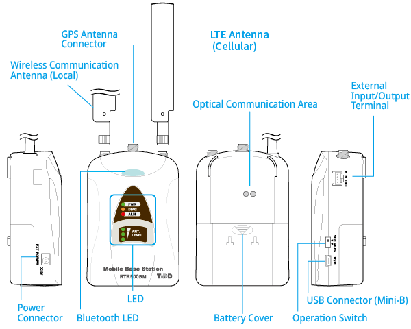
The RTR500BM transmits the measured data collected wirelessly from target Remote Units to the cloud service T&D WebStorage Service via 4G data communication, which enables remote monitoring, warning monitoring, and device settings on the cloud.
It is also equipped with Bluetooth® and USB communication for making settings, which can be done via smartphone or PC.
Here is a description of the device. For details about settings see [T&D 500B Utility Mobile App] or [RTR500BM for Windows].
| Compatible Devices | |
|---|---|
| Remote Units | RTR500B Series Data Loggers: RTR501B/502B/503B/505B/507B (Including L Type) RTR-500 Series Data Loggers:* RTR-574/576 (Including S Type), Discontinued: RTR-501/502/503/507S/505-Pt/505-TC/505-mA/505-V/505-P (Including L Type) |
| Repeaters | RTR500BC (Discontinued*: RTR-500) |
| * RTR-500 Series loggers and Repeaters do not have Bluetooth capability. | |
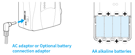
Included: LTE Antenna CSR-0011, USB Cable US-15C, AA Alkaline Battery LR6(x4), AC Adaptor AD-05A3 or AD-05C1, Registration Code Label, Manual Set (Warranty Included)
SIM Card Preparation
Please purchase a SIM card that meets the following requirements:
- Size: Nano SIM
For the supported SIM cards, contact your local T&D distributor. - The card has been or can be activated
- SIM which supports 4G data communication
If you wish to receive warning messages via SMS, then you will need a card/contract supporting SMS.
The SMS warning function is supported by firmware version R.01.00.06 or later - Contracted SIM card with a minimum speed of 200Kbps
When purchasing a SIM card, you may be asked for the IMEI number. The IMEI number for your RTR500BM can be found in the software/app as shown below:
T&D 500B Utility - [System] - [Device Info]
RTR500BM for Windows - [RTR500BM Settings Utility] - [Settings table] - [Version]
SIM Card Installation/Removal
- When inserting or removing a SIM card, avoid exposure to static electricity.
- Before inserting or removing the card, make sure to disconnect all cables (AC adaptor, USB cable, and external power cable).
- Be careful not to touch or scratch the IC area of the card. This may cause poor contact.
- Make sure to insert the card in the proper direction.
Remove the battery cover to find the SIM card holder.
Place the SIM card with the IC (electrode) side down and the notch to the lower left, and slide it to the left.

- Slide it completely left until you hear a "click" sound. Incomplete or improper insertion may cause insufficient contact with the IC and result in a communication error.
- To remove the SIM card, press in with your fingernail to release the lock, then carefully slide the card out of the SIM card holder.
Power
When in use connect to the power supply using the supplied AC adaptor AD-05A3 or AD-05C1.
The included batteries will serve as a backup power source in the event of a power failure. If running only on batteries, the estimated battery life is about 2 days under the following conditions: only one Remote Unit and no Repeaters, downloading data once a day, sending current readings at 10-min interval.
The optional battery connection adaptor BC-0204 can be used to connect to an external power source such as a car battery.
Power Source Conditions (BC-0204)

- Current:
-
MAX 2 A
- Voltage:
-
input DC9 − 38 V
output DC5 V
Cautions for Changing the Batteries
- If the PWR LED is blinking, a communication is in progress and the batteries should NOT be changed at this time.
- Do not insert or change batteries with wet hands.
- When inserting make sure no water or foreign objects get inside the case.
- When installing batteries make sure that plus and minus are correct.
- When not using the product for long periods, make sure to remove the batteries.
- When resuming use of the product or changing the battery, make sure to use the correct type and size of battery, and ensure that the battery is within the recommended expiration date.
- Please regularly check and replace any batteries installed as backup for an external power supply. Aging batteries may corrode and/or leak.
Connect the Antennas
Remove the protective covers from the antenna connectors (LOCAL and CELLULAR) on the unit, and connect the supplied LTE Antenna CSR-0011.

If you wish to use the GPS function, please purchase a GPS antenna in advance. (T&D Corporation does not handle or sell GPS antennas.) Remove the protective cover from the antenna connector (GPS) on the unit, and connect the GPS antenna.
GPS Antenna Connector: SMA Female Jack
Power Supply: 3.3 V
LED Display and Operation Switch
| Status | Details | |
|---|---|---|
| PWR (Power) Green |
BLINKING | Running on battery power only |
| ON | Running on AC Adaptor or external power source Connected via USB |
|
| BLINKING (rapidly) |
During communication via mobile network, short range radio communication, or USB connection | |
| OFF | In low energy consumption mode (functions not operable) | |
| DIAG (Diagnosis) Orange |
ON | No SIM card inserted / Poor SIM card contact |
| BLINKING | Starting up after power on No Remote Units have been registered Auto-download of recorded data cannot be carried out due to other improperly made settings or unmade settings |
|
| ALM (Alarm) Red |
BLINKING | A measurement has exceeded one of the set limits
|
| ANT. LEVEL (4G Network Reception Level) Green |
ON | 3: Strong 2: Average 1: Weak |
| OFF | Outside of communication range | |
| Bluetooth Blue |
ON | Bluetooth function ON |
| OFF | Bluetooth function OFF | |
| BLINKING | BLINKING: During Bluetooth communication with a mobile device BLINKING (rapidly): During command communication execution |
|
|
||
| Run | The following functions are operable: Auto-Downloading and Sending of Recorded Data, Warning Monitoring, and Auto-Sending of Current Readings. |
|---|---|
| STBY (Standby) | The unit is in a low energy consumption mode and functions are not operable. |
| In order to prevent unnecessary or unexpected data transmission, please leave the operation switch to STBY position until the units have all been set up and ready for communication See: [RTR500BM for Windows] - [Device Installation] section of this Help | |
External Input/Output Terminal
By connecting a buzzer, siren, lamp, or other electromagnetic contactor to the external contact input/output terminal, it is possible to be notified when a warning occurs.
The optional alarm connection cable (AC0101) is available. Please contact your local distributor for purchase.

| Contact Input (for external alarm input) | ① | Input Terminal | Internal Pull-up: 3 V 100 KΩ Maximum Input Voltage: 30 V |
|---|---|---|---|
| ② | GND | ||
| Contact Output (OUT) | ③ | Output Terminal (for external alarm output) | PhotoMOS Relay Output OFF-State Voltage: AC/DC 50 V or less ON-State Current: 0.1 A or less ON-State Resistance: 35 Ω |
| ④ | GND |
RTR500BM System Integration
T&D can provide interested users with RTR500BM communication specifications and file formats info for recorded data (TRZ format) and current readings data. This information can be integrated into a customer developed system or application.
Please contact your local Distributor.
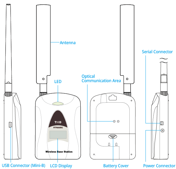
RTR500BC
Using as a Base Unit
Connect the RTR500BC to your computer with the included USB cable and collect data via wireless communication.
Here is a description of the device. For details about settings see [RTR500BC for Windows].
| Compatible Devices | |
|---|---|
| Remote Units | RTR500B Series Data Loggers: RTR501B/502B/503B/505B/507B (Including L Type) RTR-500 Series Data Loggers: RTR-574/576 (Including S Type), Discontinued: RTR-501/502/503/507S/505-Pt/505-TC/505-mA/505-V/505-P (Including L Type) RTR-600 Series Data Loggers*: RTR-602S/602L/602ES/602EL, Discontinued: RTR-601-110/130/E10/E30 |
| Repeaters | RTR500BC, (Discontinued: RTR-500) |
| * Customers wishing to use the RTR500BC as a Base Unit in conjunction with the RTR-600 series devices, please contact your local Distributor for the communications protocol specifications to write your own software. | |
Using as a Repeater
If short range wireless communication cannot successfully be carried out due to obstacles, or if you wish to extend the range, Repeater(s) can be added between Base and Remote Unit(s).
- To register a device as a Repeater use the dedicated application for the Base Unit being used.
- When using an RTR500BW or RTR500BM as a Base Unit, it is also possible to register the Repeater (RTR500BC) via Bluetooth or the cloud using the mobile app T&D 500B Utility
| Compatible Devices | |
|---|---|
| Base Units | RTR500B Series: RTR500BW, RTR500BM, RTR500BC RTR-500 Series (Discontinued): RTR-500NW, RTR-500AW, RTR-500MBS-A, RTR-500, RTR-500DC |
Included: USB Cable US-15C, Manual Set (Warranty Included)
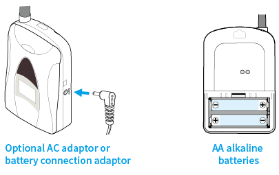
Power
When using the RTR500BC as a Repeater, the power supply options are as follows.
- Alkaline battery (not included): It can be run on 2 AA alkaline batteries for about 6 months (when wireless communication is carried out for 5 minutes every day). Battery life shortens depending on the frequency of communication.
- Optional AC adaptor AD-06A1 or AD-06C1
- Optional battery connection adaptor BC-0204: Can be used to connect to an external power source such as a car battery.
When using the RTR500BC as a Base Unit, it works on the USB bus power and it is not necessary to use another power source.
Power Source Conditions (BC-0204)
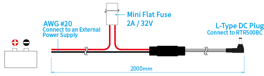
- Current:
-
MAX 2A
- Voltage:
-
input DC9 - 38V
output DC5V
Cautions for Changing the Batteries
- If the LED is blinking a communication is in progress and the batteries should NOT be changed at this time.
- Do not insert or change batteries with wet hands.
- When inserting make sure no water or foreign objects get inside the case.
- When installing batteries make sure that plus and minus are correct.
- When not using the product for long periods, make sure to remove the batteries.
- When resuming use of the product or changing the battery, make sure to use the correct type and size of battery, and ensure that the battery is within the recommended expiration date.
- Please regularly check and replace any batteries installed as backup for an external power supply. Aging batteries may corrode and/or leak.
About the LED Display
BLINKING indicates that communication is in progress.
- Green:
-
Communicating with Remote Units or Repeaters via short-range wireless
- Blue:
-
Communicating with the T&D 500B Utility mobile app via Bluetooth
LCD Display


Communication Status
BLINKING: Communication is in progress (linked with the LED indicator)

Passcode Lock
ON: Bluetooth communication is enabled (protected by a passcode)
OFF: Bluetooth communication is disabled

Power Supply Status
ON: Operating on external power (USB bus power, AC adaptor, car battery, etc.)
OFF: Operating on batteries

Battery Warning
BLINKING: Battery is low; replace the batteries as soon as possible.
ON: Battery level is too low to operate.
OFF: Battery level is sufficient.
- See: [Power]-IMPORTANT (Cautions for Changing the Batteries)

Device Info / Operational Messages
Shows whether the device is operating as a Base Unit or a Repeater, along with operational messages.
For details see [Operational Messages] below.
Operational Messages

BAS (Base Unit)
Displayed when the device is operating as a Base Unit.

RPT (Repeater)
Displayed when the device is operating as a Repeater. (Initializing the Repeater changes the display to [BAS].)
During operation, [RPT]-[GR*¹]-[No*²] are shown in rotation.

*1 [GR] is a group name that can be displayed only when the Repeater is registered under an RTR500BW or RTR500BM Base Unit. This name can be set in the [LCD Display] option during Repeater registration. If no name is set, the display will alternate only between [RPT] and [No].
*2 [No] indicates the Repeater number automatically assigned in order of registration.

Unbootable Status
Displayed when there is not enough battery voltage to boot the device.

Device Start
Displayed under the following conditions:
- When power is turned on from a state where there was no power
- When a Reset Command was sent by the application
- When a firmware update has been completed

Firmware Update in Progress
When a firmware update is in progress, the following is shown in rotation: 
Checking the Battery Level
Battery level can be checked via Settings Utility software for the Base Unit.
- It can also be checked on a smartphone via Bluetooth
-
You can check the battery level of a device in the Settings Menu of the T&D 500B Utility by going to [Base Unit / Repeater Settings] - [Wireless Route] tab.
- Check by connecting to a PC via USB
-
Connect the Repeater directly to a PC with a USB cable and in the Settings Utility for the Base Unit you are using you can find info for registered Repeaters. The battery level will appear as a number from 0-5.
RTR500BC System Integration
T&D can provide interested users RTR500BC communication specifications and file formats info for recorded data (TRZ format) and current readings data. This information can be integrated into a customer developed system or application.
Please contact your local Distributor.